LM-79 Moving Detector Goniophotometer (Mirror Type C)
LSG-6000

High Precision Rotation Luminaire Goniophotometer
LSG-1890B

High Precision Rotation Luminaire Goniospectroradiometer
LSG-1890BCCD

Goniophotometer for Automotive and Signal Lamps
LSG-1950

Goniophotometer for Traffic Signal Lamps
LSG-1950S

Compact Goniophotometer
LSG-1200A

Near Field Moving Detector Goniophotometer
LSG-1900B
Select an organization
to browse standards
1. What is a conducted disturbance test?
1.1 Introduction of conducted interference:
Electromagnetic interference (EMI)-The interference signals generated by electronic devices are transmitted through wires or public power lines, and mutual interference is called conducted interference. Conducted interference has brought confusion to many electronic engineers. How to solve the conducted interference? Find the right method and you will find that the conducted interference is actually very easy to solve. Just increase the number of sections of the EMC filter in the power input circuit, and appropriately adjust the filter of each section. The parameters of the device can basically meet the requirements. The organizers of the Seventh Seminar on Circuit Protection and Electromagnetic Compatibility summarized eight countermeasures to solve the problem of dealing with conducted interference.

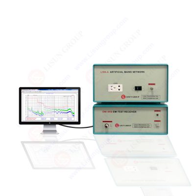
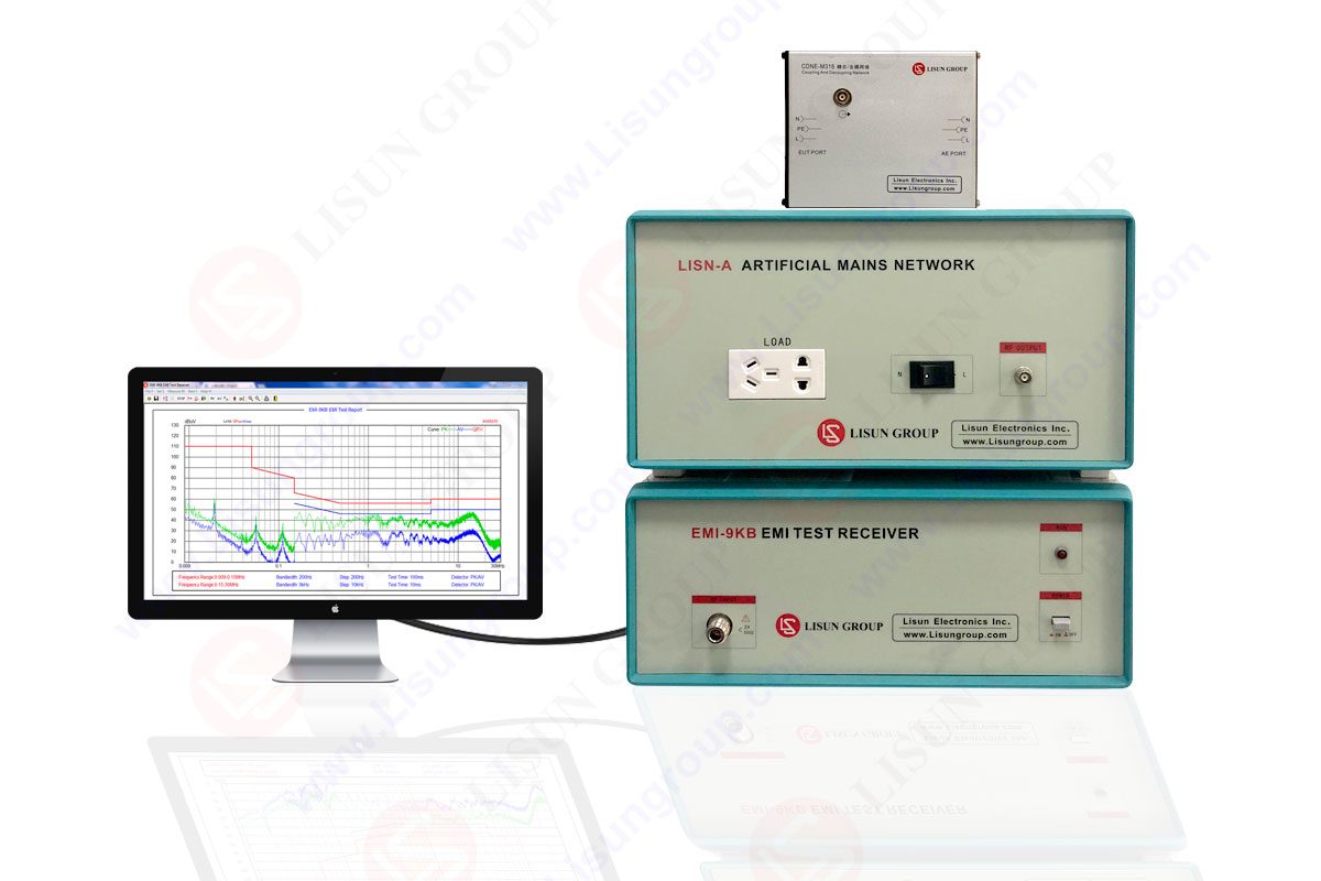
EMI-9KB_EMI Receiver System
2. What EMI electromagnetic interference system includes and which standards fully meet:
2.1 EMI electromagnetic interference system includes the following:
The electromagnetic interference test system includes a fully automatic EMI receiver, which is the core component of EMI (electromagnetic interference) testing. EMI-9KB Electromagnetic Interference System is made of fully enclosed structure and strong conductive material to ensure high shielding effect. Since the EMI system adopts the latest technology, the electromagnetic interference problem of the equipment itself has been well solved.
2.2 Standards that EMI electromagnetic interference systems meet:
The EMI Test System EMI-9KB fully meetsCISPR15:2018, CISPR16-1, GB17743, FCC, EN55015 and EN55022.
3. How to solve the EMI conduction anti-interference problem?
3.1 Minimize the effective area of each loop

Loop current creates current disturbance(figure 1)
Conducted interference is divided into differential mode interference DI and common mode interference CI. Let’s first look at how conducted interference occurs. As shown in Figure 1, loop currents generate conducted disturbances. There are several loop currents in it. We can regard each loop as an induction coil, or the primary and secondary of a transformer coil. When a current flows in one loop, an induced electromotive force will be generated in another loop. , resulting in interference. The most effective way to reduce interference is to minimize the effective area of each loop.
3.2 Shield and reduce the area of each current loop and the area and length of the live conductor

Differential mode interference signal induced by magnetic field to loop(figure 2)
As shown in Figure 2, e1, e2, e3, and e4 are differential mode interference signals induced by the magnetic field to the loop; e5, e6, e7, and e8 are the common mode interference signals induced by the magnetic field to the ground loop. One end of the common mode signal is the entire circuit board, and the other end is the ground. The common terminal in the circuit board cannot be regarded as grounding. Do not connect the common terminal to the casing. Unless the casing is connected to the ground, otherwise, the common terminal is connected to the casing, which will increase the effective area of the radiating antenna, and the common mode radiation interference will be more serious. . The method to reduce radiated interference, one is to shield, the other is to reduce the area of each current loop (magnetic field interference), and the area and length of the charged conductor (electric field interference).
3.3 Magnetically shield the transformer to minimize the effective area of each current loop

Transformer magnetic flux leakage produces electromagnetic induction on the circuit(figure 3)
As shown in Figure 3, among all electromagnetic induction interferences, the interference generated by the leakage inductance of the transformer is the most serious. If the leakage inductance of the transformer is regarded as the primary of the induction coil of the transformer, other circuits can be regarded as the secondary of the transformer. Therefore, in the circuits around the transformer, interference signals will be induced. The method to reduce interference is to magnetically shield the transformer on the one hand, and to minimize the effective area of each current loop on the other hand.
3.4 Shield the transformer with copper foil

Shield the transformer with copper foil (Figure 4)
As shown in Figure 4, the shielding of the transformer is mainly to reduce the electromagnetic induction interference generated by the leakage inductance magnetic flux of the transformer to the surrounding circuits, as well as the electromagnetic radiation interference generated externally. In principle, non-magnetically conductive materials cannot directly shield the leakage flux, but copper foil is a good conductor. Eddy current will be generated when the alternating leakage magnetic flux passes through the copper foil, and the direction of the magnetic field generated by the eddy current just in the opposite direction to the leakage flux, part of the leakage flux can be offset, so the copper foil can also play a good shielding effect on the magnetic flux.
3.5 Adopt two-wire transmission and impedance matching

Reduce EMI in the line
As shown in Figure 5, if the currents of two adjacent wires are equal in magnitude and opposite in direction, the magnetic lines of force generated by them can cancel each other. For circuits with serious interference or easily interfered, try to use two-wire transmission signals, do not use the common ground to transmit signals, the smaller the common ground current, the less the interference. When the length of the wire is equal to or greater than a quarter wavelength, impedance matching must be considered in the transmission line of the signal. Unmatched transmission lines will generate standing waves and cause strong radiation interference to surrounding circuits.
4. What are the optional instruments and calibration report used with LISUN EMI-9KC / EMI-9KB / EMI-9KA?
4.1 Option instruments to work with the EMI-9KC, EMI-9KB and EMI-9KA EMI receivers:
• LISUN LSP-500VARC/LSP-1KVARC Pure Sine Wave AC Power Source for EUT
• LISUN SDR-2000B Magnetic Shielding Cabinet for the EMI Receiver System
• LISUN VVLA-30M Three Loop Antenna to test 9k-30MHz Radiation
• LISUN AB-CLP Absorbing Clamp to test the Home Applications & motor tools
4.2 The calibration report for the conducted EMI test system is as follows, more details can be found in the calibration report on our website.

EMI-9KB calibrate certificate

EMI-9KB calibrate certificate
Summarize:
• The EMI-9KB is an automatic EMI receiver system for EMI (Electromagnetic Interference) radiation conduction or conducted emissions testing.
• The EMI-9KB EMI receiver is produced by the full closure structure and strong electro-conductibility material, which has high shielding effect. Due to the new technology for the EMI Test System, it solved the instrument self-EMI problem. The test results are according to the international format test report.
Lisun Instruments Limited was found by LISUN GROUP in 2003. LISUN quality system has been strictly certified by ISO9001:2015. As a CIE Membership, LISUN products are designed based on CIE, IEC and other international or national standards. All products passed CE certificate and authenticated by the third party lab.
Our main products are Goniophotometer, Integrating Sphere, Spectroradiometer, Surge Generator, ESD Simulator Guns, EMI Receiver, EMC Test Equipment, Electrical Safety Tester, Environmental Chamber, Temperature Chamber, Climate Chamber, Thermal Chamber, Salt Spray Test, Dust Test Chamber, Waterproof Test, RoHS Test (EDXRF), Glow Wire Test and Needle Flame Test.
Please feel free to contact us if you need any support.
Tech Dep: Service@Lisungroup.com, Cell/WhatsApp:+8615317907381
Sales Dep: Sales@Lisungroup.com, Cell/WhatsApp:+8618117273997

LISUN’s Motor-Operated Tool | Power Tool Testing solutions strictly comply with a range of core international standards, providing full support for safety and electromagnetic compatibility (EMC)...

LISUN’s transformer test solutions meet IEC 61558-1, IEC 60076-1, IEC 62041 standards. Covering safety, performance, EMC tests, ensuring transformers comply with global requirements.

LISUN’s household and appliance switch testing solutions meet IEC 60669, IEC 61058, IEC 62271 standards. Covering electrical, mechanical & EMC tests for global compliance.

LISUN provide full test solutions for HID lamp, including integrating sphere system, goniophotometer system, EMI EMC chamber, HID ballast tester, electrical safety test, etc.

Lisun can supply full test solutions for fluorescent lamp, including integrating sphere system, goniophotometer system, EMI EMC test, electronic ballast tester, electrical safety test, etc.

For the CFL design and manufactory, LISUN can supply a full quality control test solution, including photometric, colorimetric, electricity, flicker, IES candela distribution, surge test, electrical...

 中文简体
中文简体