
LM-79 Moving Detector Goniophotometer (Mirror Type C)
LSG-6000

High Precision Rotation Luminaire Goniophotometer
LSG-1890B

High Precision Rotation Luminaire Goniospectroradiometer
LSG-1890BCCD

Goniophotometer for Automotive and Signal Lamps
LSG-1950

Goniophotometer for Traffic Signal Lamps
LSG-1950S

Compact Goniophotometer
LSG-1200A

Near Field Moving Detector Goniophotometer
LSG-1900B
Select an organization
to browse standards
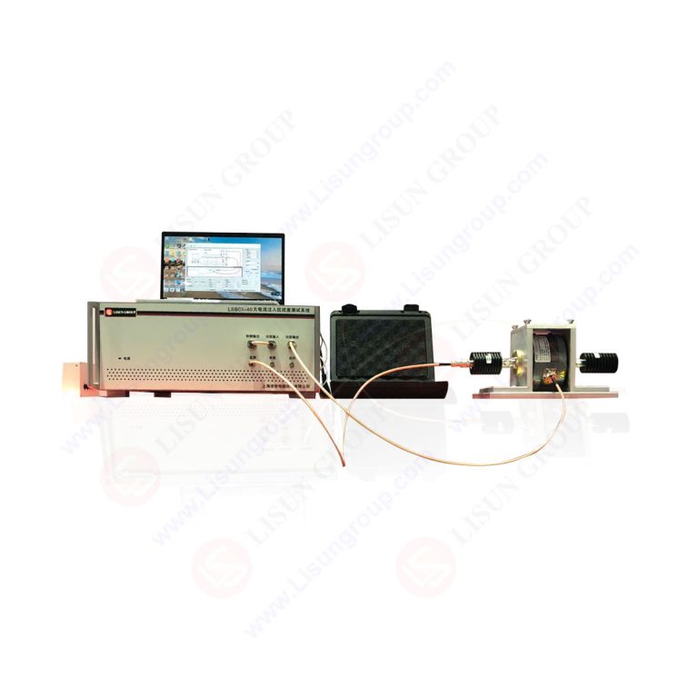

Product No: LSBCI-40
The LSBCI-40 Bulk Current Injection (BCI) test system is an electromagnetic immunity tester designed by LISUN specifically for the automotive electronics, rail transit, and industrial control sectors. The function is to simulate the radio frequency (RF) interference experienced by electronic devices in complex electromagnetic environments. By injecting a specified RF current into the cable bundle of the device under test (DUT), the system assesses the device’s operational stability under RF interference and proactively identifies functional anomalies (such as signal distortion and control failure) caused by electromagnetic compatibility issues, providing critical testing support for products passing international EMC certification.
Standards:
| Standards NO. | Standards Name |
| ISO 11452-4:2020 | Road vehicles — Component test methods for electrical disturbances from narrowband radiated electromagnetic energy — Part 4: Bulk current injection (BCI) |
| SAE J1113/4-2020 | SAE Standard — Electromagnetic Compatibility Measurement Procedures and Limits for Components and Subsystems — Part 4: Bulk Current Injection (BCI) |
| GB/T 33014.4-2016 | 道路车辆 电气 / 电子部件对窄带辐射电磁能的抗扰性试验方法 第 4 部分:大电流注入 |
System configurations and technical parameters:
| 1. Test host | |
| Test Current | Open-loop test (substitution test) ≤300mA; Closed-loop test ≤200mA (fully automatic calibration, fully automatic test and output power monitoring during the test) |
| Output Impedance | 50Ω |
| Voltage Standing Wave Ratio | ≤1.2 |
| Chinese and English software | Support Win7,Win8 and Win10,Win11 |
| 2. Signal Source (built-in) | |
| Frequency | 9kHz~3GHz |
| Output Level | -60~10dBm |
| Unmodulated signal | Continuous Wave |
| Modulation Mode | Amplitude modulation frequency:0.1Hz~500kHz;Modulation Depth:0~100% |
| Pulse modulation frequency:0.1Hz~20kHz;Duty Cycle:1~100% | |
| 3. Power Amplifier (built-in) | |
| Output Frequency | 100kHz~400MHz (Scalable to 1GHz) |
| Maximum Output Power | 125W(Linear Power) |
| Harmonic | <15dBc |
| 4. Three Channels Power Meter (built-in) | |
| Input Frequency | 9kHz~3GHz |
| Input Power | -40dBm~+30dBm |
| 5. Directional Coupler (built-in): coupling degree 40dB | |
| 6. LIS-BCP410 Current Injection Probe: Frequency range 10kHz~400MHz; max attenuation 10dB; N-type coaxial output terminal | |
| 7. LIS-CCF500 Current Injection Probe Clamp: Frequency range DC~500MHz; voltage standing wave ratio 2:1 | |
| 8.LIS-BCM410 Current Monitor Probe: Closed-loop testing method for high-current BCI testing; frequency range 10kHz~400MHz; maximum current 100A | |
| 9. LIS-AN100A Artificial Power Network: Frequency range: 10kHz~108MHz; Maximum operating voltage: 250VAC/100VDC; Maximum operating current: 100A; Equivalent circuit (5µH+1Ω)||50Ω | |
| 10. Test Table (optional with additional cost) | |
| BCI Test Table | 2*1*0.9m |
| BCI Grounding | The coupling plate edge strips are grounded at intervals of 300mm, and the aspect ratio of each ground strip is 7:1. Material: brass |
| Reference Ground Plane | 2*1*2mm,Material: Brass |
| 11. Electromagnetic shielding cabinet: SDR-4000B, internal dimensions are 4000*1200*1800mm (optional with additional cost, the dimensions can also be designed according to customer requirements) | |
Part 1: Test steps:
A. Before the test, verify that the disturbance current generated by the current injection probe meets the requirements in the calibration fixture, and then clamp the current probe to the specified position of the harness to be tested
B. Apply interference to the harness based on the forward power obtained by calibration. The current intensity is not monitored during the test, and the forward power is no longer adjusted
C. The length of the harness and the relative distance between the current injection probe and the harness to be tested will affect the coupling degree of the disturbance electromagnetic field on the harness to be tested
Part 2: Test result determination: The open-loop method is mainly divided into 5 levels, each level represents a different test result.
A. The function or performance of the EUT has been normal without any abnormality.
B. All functions or performances are in the interference state, one or more functions/performances deviate from the specified tolerance, but all functions or performances are restored to the specified tolerance limit after the interference is removed, and there should be no abnormality in the stored data.
C. One or more functions/performances are lost, but the EUT automatically recovers to normal mode after the interference is applied.
D. One or more functions/performances are lost, but they are restored to normal mode through human intervention after the interference is applied.
E. One or more functions/performances are lost, but they cannot be restored to normal mode after the interference is applied.
Part 3: Test system layout (refer to ISO 11452-4 Figure 2, Figure 1 and Figure 3):
1. Reference ground plane: The reference ground plane uses a metal plate with a thickness greater than 0.5mm, preferably brass. The length and width of the test bench and the reference ground plane are at least 1700×1000mm; the impedance of the grounding material is not greater than 2.5 milliohms, and the interval is not greater than 300mm;
2. Artificial power network: For remote grounding, 2 artificial power networks are required, and for near-end grounding, only 1 artificial power network (connected to the positive pole) is required;
3. Placement of EUT: The product under test should be placed on an insulating material with a low dielectric constant (not greater than 1.4) and a thickness of 50 (±5) mm. The total length of the test harness EUT and the simulated load harness should be: 1000 (±100) mm, and the test harness should be placed on an insulating material with a dielectric constant (not greater than 1.4) and a thickness of 50 (±5) mm.
4. High current injection probe: The distance d between the injection probe and the EUT is as follows:
d=(150±10)mm
d=(450±10)mm
d=(750±10)mm
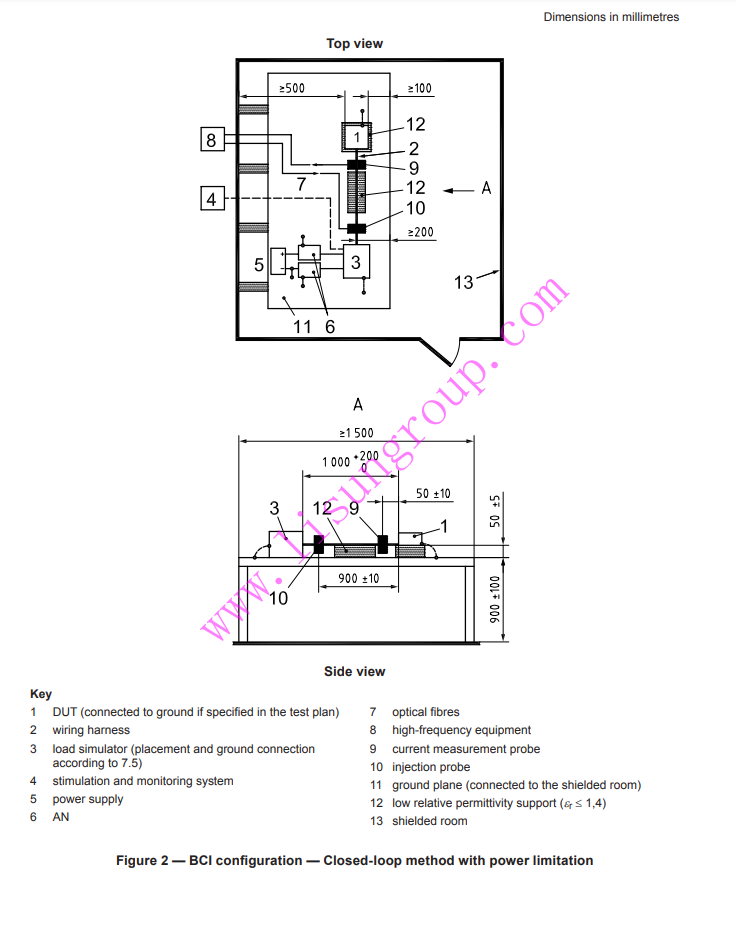
ISO 11452-4:2020 Figrue 2
LISUN's Motor-Operated Tool | Power Tool Testing solutions strictly comply with a range of core...
To simulate EMI stress in the intended operating environment, a bulk current injection test is a...
What Is A Bulk Current Injection: High current injection is a testing technique in automotive...
In China, cars are becoming more and more popular. With the development of automobile industry,...
Electrical and radio-frequency disturbances occur during normal operation of many items of motor...
Abstract This article provides an in – depth exploration of the Bulk Current Injection Test...

 中文简体
中文简体