LM-79 Moving Detector Goniophotometer (Mirror Type C)
LSG-6000

High Precision Rotation Luminaire Goniophotometer
LSG-1890B

High Precision Rotation Luminaire Goniospectroradiometer
LSG-1890BCCD

Goniophotometer for Automotive and Signal Lamps
LSG-1950

Goniophotometer for Traffic Signal Lamps
LSG-1950S

Compact Goniophotometer
LSG-1200A

Near Field Moving Detector Goniophotometer
LSG-1900B
Select an organization
to browse standards
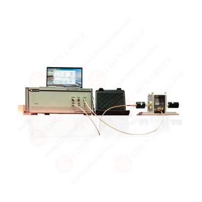
To simulate EMI stress in the intended operating environment, a bulk current injection test is a conducted RF immunity test in which a modulated signal is injected into cables through a current injection probe.
The DUT’s (and related PCB and external components’) resistance to electromagnetic fields connected to the communications line wire harnesses may be evaluated using bulk current injection (BCI).
To guarantee compliance and product dependability while subjected to conducted EMI disturbances through an injection probe, a continuous RF immunity test known as the BCI test is used. Businesses, the military, and the auto industry all do this immunity test at different levels and with different frequencies and restrictions.
Description
A bulk current injection test is performed to ensure that RF signals coupled into interconnecting cables and power supply lines will not degrade performance or deviate from the specifications of the equipment under test.
Moreover, it will reveal the malfunction’s unique amplitude and frequency. Calibration fixtures are used to set the forward power into the injection probe, which generates specified currents in the calibration fixture to account for the widely varying circuit impedances and resonances in cables. A current monitoring probe detects the actual amount of current injected.

Figure: Bulk current injection test system
BCI Testing
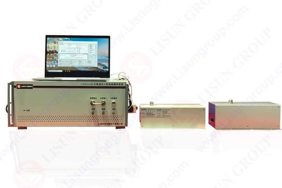
The initial stage, whether the closed loop or replacement technique, is always the LSBCI-40 setup’s calibration. This procedure saves the test levels and their appropriate power settings for further use during the test.
How BCI is measured
Depending on the metric and standard being used, several different methods exist to quantify the injection of bulk current. Volts are utilized in commercial applications because they are calibrated to a certain amount of energy.
Measurements of the current in the cables used for feedback loops in vehicles and military equipment are often made in milliampere-seconds or decibels (mA or dBuA).
BCI Test Equipment
While the specific tools used for bulk current injection tests may change depending on the nature of the tests being conducted:
1. Conducted RF System
2. Associated Attenuators & Loads
3. BCI Injection Probe & Fixture
4. Current Monitoring Probe & Fixture
Pre calibration:
Pre-calibration is performed with the device fastened to the calibration fixture to determine the forward power levels required to create the specification limits. The clamp receives power through a directional coupler from the signal source (signal generator and amplifier). The clamp forces current via a 100-ohm circuit consisting of a 50-ohm termination and a 50-ohm attenuator and spectrum analyzer/receiver at opposite ends of the fixture.
It will use the calibration fixture to secure the injection probe.
You will connect one end of the calibration fixture to a 50-ohm, 50 watt RF load, and a 50 ohm, 30 dB receiver attenuator will be needed to shield the receiver or spectrum analyzer from the signal. Both ends of the calibration fixture will have VSWR values less than 1.2:1 over the tested spectrum of frequencies.
The signal generator and power amplifier provide signals to the injection probe at various strengths. The calibrating fixture’s injection-current limitations have been previously calibrated for two different current strengths:
1. A current threshold below or above which the tested device will not fail.
2. A current that will temporarily disrupt the operation of the tested device without damaging it beyond repair or the specified limit.
Pre calibration Procedure Steps:
Injection test procedure:
SAFETY:
Use caution throughout all these exams. During these experiments, very high RF voltages and currents are produced. To avoid injury, test personnel should avoid touching any metal parts of the setup.
Every wire and every length of cable must pass the equipment test by the technical requirements. The test method will list all the wires and cables it will check. The current broadband probe should be positioned from the injection probe. For most requirements, this is around 5 cm.
Clamping current probes around bare wires requires extra caution. The test item is recommended to be de-energized before any installation or disassembly of the test equipment. If you want to further safeguard against a voltage breakdown, you should route all probe wires via the center of the probes’ aperture. Connectors for the current probe and its cables should not touch the earth or any nearby wires since they are not insulated.
Bulk Current Injection Probes
The primary ways LSBCI-40 probes are sorted are transfer impedance, frequency range, power management, and standard compliance. When calibrating a system, a steady impedance is provided by the fixture used for calibration. The probe’s clamp-on hinge allows it to open and secure around the fixture before being linked to the RF system. These probes are not compatible with any other kind of calibration fixture.
RF Current Monitoring Probes
1. Measuring radio frequency (RF) currents on cables or wires without making physical contact using circular, windowed devices called RF current monitoring probes is possible.
2. Current probes have a wide variety of sensitivity, power, and frequency capabilities.
3. The radio frequency (RF) range of 10 kHz to 400 MHz is of primary interest for bulk current injection testing. In RF immunity applications, current monitoring probes are often employed to measure the amount of RF energy injected into the related cable following the injection probe.
4. The probes most suited to satisfy testing demands will be determined by the criteria and requirements for testing BCIs that will be detailed later. The monitoring probe or probes must include the range of frequencies tested.
Software
For RF testing and calibration over a wide variety of frequencies, EMC/EMI software is necessary. It may use the front panel of a conducted RF system or a laptop running an appropriate program for this purpose. The program needs access to the corresponding drivers for any standalone components (signal generator, spectrum analyzer, etc.) to be able to exchange data with them.
Conducting BCI Testing
Calibration is the initial stage in administering a LSBCI-40 evaluation, regardless of whether the replacement or closed loop approach is employed. After the calibration is complete, the accompanying procedure and any additional standard or special test requirements will be the primary focus of the subsequent testing.
It must take attenuation and safety measures before performing any test, including calibration. While many systems are built with over-testing protection, equipment damage may still occur if the right connections and procedures aren’t used.
RF Signal Modulation
Amplitude modulation (AM) and amplitude modulation with peak conservation (AMPC) are the two types of modulation utilized for signals in the BCI test (AM PC). The AM PC signal technique in automobile applications is often used since its modulation peak coincides with the CW signals.
Substitution method for BCI testing
The power levels supplied during calibration are used as the primary factor in the replacement approach for BCI testing, and it may limit the current based on the impedance of the EUT line.
Calibration involves the system determining the amount of power required to induce a specified amount of current into a 50 Ohm load throughout a certain frequency range. Testing of the EUT/DUT will therefore use the same power level associated with the 50 Ohm impedance.
Closed loop method
The closed loop technique (also known as a leveling loop) uses a current monitoring probe to assess current levels and then adjusts the RF power to maintain a constant current through the connected connections.
Adjustments are made based on readings from the current monitoring probe (often in mA or dBA). The closed-loop approach is utilized to maintain constant current levels based on power estimations derived from the calibration procedure.
Since DUT/EUT with greater impedance may demand much more power, the power is adjusted within a tolerance to guarantee that the required power is not exceeded.
Pre-compliance/Troubleshooting Immunity Failures
The costs associated with radiated immunity testing may be prohibitive, and there is typically little time to make significant changes to the product while it is at the lab. Sometimes, especially at lower frequency ranges, a BCI test may provide findings comparable to those obtained with a EUT/DUT subjected to the same physical or environmental stresses.
Commercial radiated and performed immunity tests provide similar test values (10V/m and 10V, for example). This makes it possible to perform RF testing for diagnosing radiated EUT/DUT faults at much lower prices. Source impedance and frequency of interest will be the two most important factors in this testing.
This technique excels during radiated testing when coupling onto cables leading to the EUT/DUT is more likely to occur at lower frequencies. The likelihood of successful coupling onto wires decreases as frequency increases, making this approach less attractive. LISUN has the best test system
Troubleshooting BCI Test Setup
Check Connections
When something isn’t working well in a system configuration, the first thing is to double-check all of the connections. A dual directional coupler with an external amplifier emphasizes this feature’s significance since it may toggle many more connections.
Be careful to double-check the threading of the RF connectors when you’re inspecting the other connections. It may be difficult to see whether the connection is screwed properly if the parts are old or worn. It may make each connection secure by manually tightening it.
Verify Attenuators
RF Most attenuators are rather sturdy, although damage from overloading or transport may still occur. If an attenuator stops functioning, it won’t be able to calibrate at any volume. It is recommended that while checking the connections, each attenuator be replaced separately and the calibration conducted to discover which one is faulty.
It is also feasible to rule out attenuators as potential sources of interference by testing them before installing them in the configuration. Use a power meter and sensor to ensure you have the right amount of attenuation.
Check Software
Many different types of LSBCI-40 needs may be met by the user interface and EMC/EMI software of test equipment. The complexity of test techniques and settings and inexperience with software may lead to a wide variety of problems.
A failed setup might result from a mistake as little as a typo in the data entered or a wrong choice of criteria. Before initiating a new testing procedure, it is recommended that the criteria be verified. It may often fix software problems by checking the user manual or other resources to ensure certain requirements have been met.
RF Amplifier Evaluation
The RF power amplifier is a delicate part of any RF testing setup. The life expectancy of amplifiers varies depending on the manufacturer, but they should all be tested often to ensure they are still functioning properly.
Discrepancies in the power ratings might indicate that the amplifier is at fault. The amplifier may not pass a frequency test or may not reach a specified volume level depending on the severity of the damage.
Lisun Instruments Limited was found by LISUN GROUP in 2003. LISUN quality system has been strictly certified by ISO9001:2015. As a CIE Membership, LISUN products are designed based on CIE, IEC and other international or national standards. All products passed CE certificate and authenticated by the third party lab.
Our main products are Goniophotometer, Integrating Sphere, Spectroradiometer, Surge Generator, ESD Simulator Guns, EMI Receiver, EMC Test Equipment, Electrical Safety Tester, Environmental Chamber, Temperature Chamber, Climate Chamber, Thermal Chamber, Salt Spray Test, Dust Test Chamber, Waterproof Test, RoHS Test (EDXRF), Glow Wire Test and Needle Flame Test.
Please feel free to contact us if you need any support.
Tech Dep: Service@Lisungroup.com, Cell/WhatsApp:+8615317907381
Sales Dep: Sales@Lisungroup.com, Cell/WhatsApp:+8618117273997

LISUN’s Motor-Operated Tool | Power Tool Testing solutions strictly comply with a range of core international standards, providing full support for safety and electromagnetic compatibility (EMC)...

 中文简体
中文简体