LM-79 Moving Detector Goniophotometer (Mirror Type C)
LSG-6000

High Precision Rotation Luminaire Goniophotometer
LSG-1890B

High Precision Rotation Luminaire Goniospectroradiometer
LSG-1890BCCD

Goniophotometer for Automotive and Signal Lamps
LSG-1950

Goniophotometer for Traffic Signal Lamps (Economical Model)
LSG-1950S

VAD Fire Alarm Visual Alert Device Goniophotometer
LSG-1930
Goniophotometer for Airfield Lighting
LSG-1940

Compact Goniophotometer
LSG-1200A

LED Goniophotometer
LSG-1100
Near Field Moving Detector Goniophotometer
LSG-1900B
 LEDs and Luminaire Test Solutions
 LM-79 and LM-80 Test Solutions
 LED Driver Test Solutions
 Household Appliances Test Solutions
 Mobile and Network Test Solutions
 Automotive Electronics Test Solutions
 Audio-Video and IT Test Solutions
 Cable and Wire Test Solutions
 Plugs and Sockets Test Solutions
 Power Switch Test Solutions
 Transformer Test Solutions
 Electric Toys Test Solutions
 Energy Meter Test Solutions
 Motor-Operated Tool Test Solutions
Select an organization
to browse standards
Abstract
In power systems and industrial electromagnetic environments, transient interferences in the form of damped oscillatory waves generated by high-voltage switching operations and High-Altitude Electromagnetic Pulse (HEMP) easily lead to abnormal operation of electrical equipment. The Damped Oscillatory Wave Immunity Tester is a special EMC testing instrument developed in accordance with GB/T 17626.18 and IEC/EN 61000-4-18 standards. Its core technology relies on capacitor pre-charging and RLC resonant circuit to reproduce standard waveforms. Taking the LISUN DOW61000-18 series Damped Oscillatory Wave Immunity Tester as the research object, this paper analyzes its circuit working principle and waveform generation mechanism, distinguishes test scenarios of slow and fast damped oscillatory waves, and elaborates its testing functions and practical applications combined with equipment parameters. It provides technical references for immunity testing of power equipment and new energy products.
1. Introduction
With the large-scale construction of smart power grids, new energy power stations and high-voltage substations, the electromagnetic environment inside power grids has become increasingly complex. Switching on and off of high-voltage disconnectors and circuit breakers, as well as the intrusion of High-Altitude Electromagnetic Pulse (HEMP), will generate periodically attenuated damped oscillatory waves on busbars and cable lines. Such transient interferences can conduct to secondary equipment along power lines and signal wires, causing maloperation of relays, communication interruption, controller crash and other failures.
To quantitatively evaluate the tolerance of electrical equipment to such interferences, domestic and foreign authorities have successively issued GB/T 17626.18 and IEC/EN 61000-4-18 standards, which specify test methods, waveform parameters and test levels for damped oscillatory wave immunity.
As the core instrument for such tests, the Damped Oscillatory Wave Immunity Tester can accurately reproduce on-site interference waveforms under laboratory conditions. The LISUN DOW61000-18 series Damped Oscillatory Wave Immunity Tester includes two main models: the basic DOW61000-18 (slow type) and DOW61000-18F (fast type), which comply with the two types of damped oscillatory waves specified in relevant standards. Widely used for detection of primary substation equipment, secondary control devices and new energy combiner cabinets, it is essential EMC testing equipment for the power industry.
2. Core Working Principle of Damped Oscillatory Wave Immunity Tester
The core waveform generation logic of the Damped Oscillatory Wave Immunity Tester is capacitor pre-charging + RLC resonant discharge + resistance damping attenuation, which perfectly generates sinusoidal envelope oscillatory waveforms with amplitude decreasing cycle by cycle and fully matches the real interference characteristics in power sites.
During equipment operation, the internal high-voltage charging unit firstly pre-charges the energy storage capacitor and stores electric energy in the form of electric field inside the capacitor. When the charging voltage reaches the set test level, the control switch turns on instantly, and the energy storage capacitor releases energy to the RLC resonant circuit composed of inductor (L), resistor (R) and capacitor (C). An ideal LC circuit can produce continuous equal-amplitude sinusoidal oscillation, while a fixed damping resistor is connected in series inside the circuit of this tester. Due to energy consumption on the resistor, the peak value of oscillatory waveforms decays continuously cycle by cycle, finally forming standard damped sinusoidal oscillatory waves.
Combined with on-site interference characteristics of power systems, this principle corresponds to two working conditions: low-frequency slow damped oscillatory waves generated by switching operations of outdoor high-voltage substation disconnectors, and high-frequency fast damped oscillatory waves caused by circuit breaker operations and HEMP intrusion. By switching circuit parameters and adjusting charging voltage and output impedance, the Damped Oscillatory Wave Immunity Tester generates two types of waveforms separately. With the built-in Coupling/Decoupling Network (CDN), oscillatory waves are injected into power ports of Equipment Under Test (EUT) via conductive coupling. After matching with special CDN modules, it can also carry out tests on signal and control ports to comprehensively verify the anti-transient-interference capability of equipment.
In terms of waveform indicators, both types of waveforms follow unified attenuation rules: the voltage of the fifth wave crest is higher than 50% of the first wave crest, and the voltage of the tenth wave crest is lower than 50% of the first wave crest. This indicator is strictly aligned with national and international standards to guarantee the validity of test results.
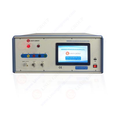
DOW61000-18
3. Parameters and Classification of LISUN DOW61000-18 Series Damped Oscillatory Wave Immunity Tester
The LISUN DOW61000-18 series contains slow and fast Damped Oscillatory Wave Immunity Tester models, which differ greatly in oscillation frequency, output voltage, rise time, output impedance and other core parameters. They are applicable to different interference scenarios and test objects respectively. The detailed core parameters are shown in Table 1 below.
Table 1 Core Parameters of LISUN DOW61000-18 Series Damped Oscillatory Wave Immunity Tester
| Parameter Item | DOW61000-18 (Slow Damped Oscillatory Wave) | DOW61000-18F (Fast Damped Oscillatory Wave) |
| Applicable Standards | IEC/EN 61000-4-18 Clause 4.2, GB/T 17626.18 Clause 4.1 | IEC/EN 61000-4-18 Clause 4.3, GB/T 17626.18 Clause 4.2 |
| Open-circuit Peak Voltage | 200V~3kV (±10%) | 450V~4.4kV (±10%) |
| Short-circuit Peak Current | 1.25A~12.5A (±20%) | 5A~80A (±20%) |
| Output Impedance | 200Ω | 50Ω |
| Oscillation Frequency | 100kHz, 1MHz (±10%) | 3MHz, 10MHz, 30MHz (±10%) |
| Voltage Rise Time | 75ns (±20%) | 5ns (±30%) |
| Repetition Rate | 100kHz: 40 pulses/s; 1MHz: 400 pulses/s | 5000 pulses/s (±10%) |
| Pulse Polarity | Positive, Negative, Automatic Alternation | Positive, Negative, Automatic Alternation |
| Built-in Coupling Network | AC 3-phase 5-wire 380V/16A, DC 300V/16A | AC 3-phase 5-wire 380V/16A, DC 300V/16A |
3.1 Slow Damped Oscillatory Wave Tester (DOW61000-18)
This model is designed for low-frequency transient interferences induced by disconnector switching and busbar reflection in substations. Its oscillation frequencies are set to 100kHz and 1MHz, matching interference frequency characteristics of large high-voltage substations (maximum 400m busbars) and conventional outdoor substations. With 200Ω output impedance, its repetition rates are set to 40 pulses/s and 400 pulses/s, which are standard compromise parameters determined by contact spacing of switches and equipment withstand energy. It is mainly used for testing power transformers and primary substation equipment to evaluate their operational stability under low-frequency damped oscillatory interference.
3.2 Fast Damped Oscillatory Wave Tester (DOW61000-18F)
This model simulates high-frequency interferences generated by rapid switching of circuit breakers and High-Altitude Electromagnetic Pulse (HEMP). Its oscillation frequency is increased to 3MHz, 10MHz and 30MHz, and the voltage rise time is shortened to 5ns, achieving faster transient response capability. The output impedance is reduced to 50Ω, and the maximum short-circuit current reaches 80A, delivering stronger interference energy. It is widely applied to medium and high voltage substation secondary protection devices, new energy power station combiner cabinets, intelligent measurement and control equipment and other precision electronic products, to verify their immunity under strong high-frequency electromagnetic pulse environments.
Both models are equipped with liquid crystal touch screens, pre-installed standard test levels and support stepped voltage adjustment. They are supplied with CNAS ISO17025 calibration certificates to meet laboratory metrological traceability requirements. For testing unshielded communication lines and control lines, users can match CDN61000-18S series coupling and decoupling networks to expand line-to-ground and line-to-line coupling test functions.
4. Application Scenarios and Test Procedures
4.1 Main Application Scenarios
The Damped Oscillatory Wave Immunity Tester serves three major industries: power grid, new energy and industrial automation. In the power industry, it conducts factory inspection of primary and secondary equipment for high/medium voltage substations. In the new energy industry, it performs immunity tests on photovoltaic and wind power station combiner cabinets and energy storage converters. In industrial fields, it undertakes EMC acceptance of factory power distribution equipment and automatic control cabinets. Meanwhile, as essential testing instruments for CE certification and domestic China Compulsory Certification (3C), they are required for products exported to EU and domestic market access.
4.2 Basic Test Procedures
• Equipment Selection: Select the corresponding model according to the service environment of Equipment Under Test. Choose the slow model for primary substation equipment and the fast model for secondary measurement & control and new energy equipment.
• Circuit Connection: Connect the Equipment Under Test to the built-in coupling/decoupling network of the instrument; match external dedicated CDN modules for signal line tests.
• Parameter Setting: Configure oscillation frequency, output voltage, repetition rate, pulse polarity and other parameters in accordance with relevant standards or product specifications.
• Loading Test: Start the instrument to output damped oscillatory waves, continuously apply interference and observe the operating status of the Equipment Under Test.
• Result Judgment: The test result is qualified if the equipment operates normally without crash, misoperation or performance degradation under interference.
5. Conclusion
Relying on the core principle of capacitor pre-charging and RLC resonant circuit, the Damped Oscillatory Wave Immunity Tester accurately reproduces typical transient interference waveforms including power system switching operations and high-altitude electromagnetic pulses, making it an indispensable testing instrument in the electromagnetic compatibility field. The LISUN DOW61000-18 series Damped Oscillatory Wave Immunity Tester strictly complies with mainstream domestic and international standards. Through classification of slow & fast models, adjustable abundant parameters and expandable configurations, it covers test demands of all types of power equipment.
Against the backdrop of continuous development of new power systems, the electromagnetic environment of power grids becomes more complex, raising higher requirements on transient anti-interference performance of electrical equipment. Wide application of the Damped Oscillatory Wave Immunity Tester can control EMC performance of products from R&D, production to testing links, effectively reduce on-site failure rates and ensure safe and stable operation of power grids, new energy power stations and industrial systems. In the future, with continuous updating of electromagnetic compatibility standards, such testers will keep upgrading towards higher frequency, larger output voltage and intelligent testing.
Tags:DOW61000-18Your email address will not be published. Required fields are marked *

 English
 中文简体
中文简体 English
 Русский
 Español
 Português
 Türkçe
 العربية
 Deutsch
 Polski
 Italiano
 Français
 한국어
한국어 ไทย
ไทย Tiếng Việt
 日本語
日本語