
LM-79 Moving Detector Goniophotometer (Mirror Type C)
LSG-6000

High Precision Rotation Luminaire Goniophotometer
LSG-1890B

High Precision Rotation Luminaire Goniospectroradiometer
LSG-1890BCCD

Goniophotometer for Automotive and Signal Lamps
LSG-1950

Goniophotometer for Traffic Signal Lamps
LSG-1950S

VAD Fire Alarm Visual Alert Device Goniophotometer
LSG-1930

Compact Goniophotometer
LSG-1200A

LED Goniophotometer
LSG-1100
 LEDs and Luminaire Test Solutions
 LM-79 and LM-80 Test Solutions
 LED Driver Test Solutions
 Household Appliances Test Solutions
 Mobile and Network Test Solutions
 Automotive Electronics Test Solutions
 Audio-Video and IT Test Solutions
 Cable and Wire Test Solutions
 Plugs and Sockets Test Solutions
 Power Switch Test Solutions
 Transformer Test Solutions
 Electric Toys Test Solutions
 Energy Meter Test Solutions
 Motor-Operated Tool Test Solutions
Select an organization
to browse standards
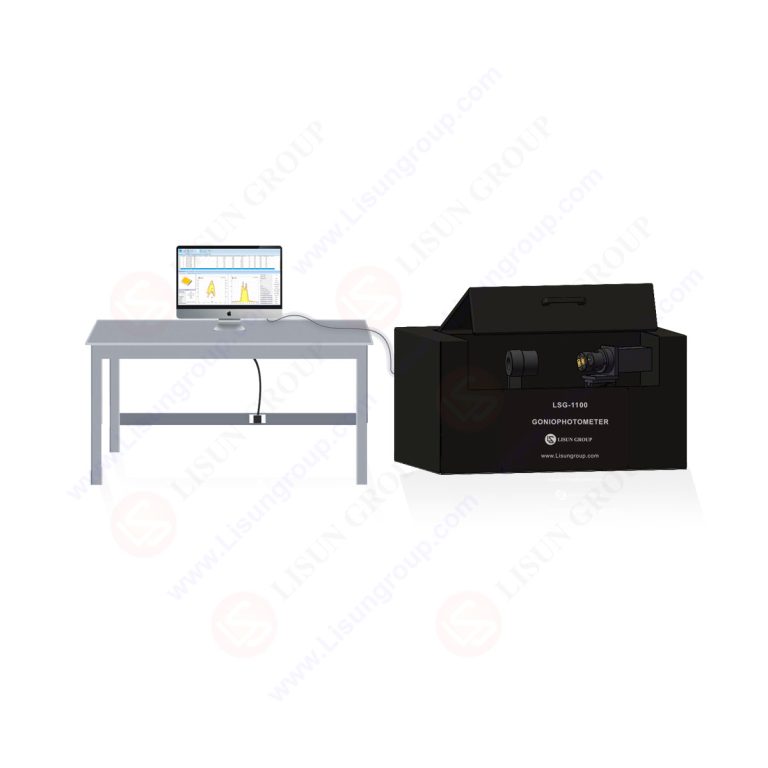
Product No: LSG-1100
The LSG-1100 LED goniophotometer is developed according to CIE 127, IEC 61341, and GD/T1 “Test Methods for Semiconductor Light Emitting Diodes,” and is specifically designed for testing the light distribution performance of small surface-mount LEDs, through-hole LEDs, and COB light sources. The software supports outputting test reports in both Chinese and English, and can export 3D light distribution curves and electrical performance test data for easy archiving and comparative analysis. It is widely used in quality inspection agencies, universities, and corporate R&D laboratories.
The LSG-1100 LED goniophotometer can test the following parameters: spatial light intensity distribution; 10%, 25%, 50%, and 75% average light intensity diffusion angles; peak light intensity, total luminous flux, and luminous efficacy; forward voltage Vf, forward current If, reverse voltage Vr, reverse leakage current Ir, and electrical power P. Optional modules can also test chromaticity parameters such as wavelength, chromaticity coordinates, peak wavelength, dominant wavelength, full width at half maximum (FWHM), and spectral curves. With different radiation probes, it can also perform angular distribution testing of the radiation intensity of infrared and ultraviolet LEDs.
Specifications:
| Items | Technical Specifications |
| Photometric Detector | VIS (380~800nm) visible light V (λ) probe, Class A, conforming to CIE pub.No.127 standard. |
| Photometric Measurement Range | Luminous intensity measurement range: 10 mcd~200 cd; Luminous flux measurement range: 1 mlm~200 lm |
| Angle Measurement Range | C-axis rotation range: 0°~360°, γ-axis rotation range: -90°~90°, capable of automatic rotation to acquire three-dimensional light intensity distribution maps. |
| Scan Interval | 0.1°, 0.5°, 1°, 5°, 10°, 45°, 90°, 180° (selectable) |
| Output Curve Format | Three-dimensional light intensity, radiation intensity distribution curves (polar coordinates, rectangular coordinates) and export IES file for DiaLux. See the test report sample here. |
| Test Distance | Distance from detector to rotation center: 100mm and 316mm (adjustable); meets CIE pub.No.127 Condition A or Condition B test conditions. |
| Mechanical positioning | Precision LED mechanical positioning device and integrated center alignment system |
| Current Test | Forward current If: 0.1mA~2000mA; Reverse current Ir: 0.01μA~200.0μA; Measurement accuracy: ±0.5% F.S. |
| Voltage Test | Forward voltage Vf: 0.01V~20.0V; Reverse voltage Vr: 0.01V~20.00V; Measurement accuracy: ±0.5% F.S. |
| Overall Dimensions | 638*442*340mm, desktop integrated structure with built-in darkroom |
| Optional Configuration 1 | Optional built-in color measurement module for colorimetric testing: LISUN model LSG-1100CCD |
| Optional Configuration 2 | The photometric detector can be equipped with LISUN Model PHOTO-NIR-1100 (800-1050nm), PHOTO-UVA-1100 (320~400nm), PHOTO-UVB-1100 (275~320nm) and PHOTO-UVC-1100 (200~275nm). |
Matching Clamps (the system includes the following clamps):
| Fixture Type | Specifications |
| CLAMP-33 LED Clamp | 7.5mm pin pitch, compatible with through-hole LEDs |
| CLAMP-36 LED Clamp | Minimum pin pitch 2mm×5mm, maximum pin pitch 6mm×5mm, compatible with small-size SMD LEDs and COB light sources. |
| CLAMP-25 LED Clamp | Maximum pin pitch of 24mm, suitable for large-size SMD LEDs and COB light sources |
Note: Different clamps are compatible with plug-in LEDs, various SMD surface mount devices, and COB devices. Customization is available based on the LED sample being tested.

LED Clamps

Test interface and test parameters

 English
 中文简体
中文简体 English
 Русский
 Español
 Português
 Türkçe
 العربية
 Deutsch
 Polski
 Italiano
 Français
 한국어
한국어 ไทย
ไทย Tiếng Việt
 日本語
日本語






