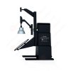
LM-79 Moving Detector Goniophotometer (Mirror Type C)
LSG-6000
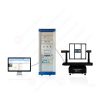
High Precision Rotation Luminaire Goniophotometer
LSG-1890B
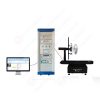
High Precision Rotation Luminaire Goniospectroradiometer
LSG-1890BCCD

Goniophotometer for Automotive and Signal Lamps
LSG-1950
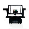
Goniophotometer for Traffic Signal Lamps (Economical Model)
LSG-1950S
VAD Fire Alarm Visual Alert Device Goniophotometer
LSG-1930
Goniophotometer for Airfield Lighting
LSG-1940
Compact Goniophotometer
LSG-1200A
LED Goniophotometer
LSG-1100
Near Field Moving Detector Goniophotometer
LSG-1900B
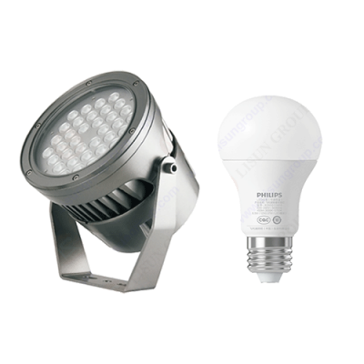 LEDs and Luminaire Test Solutions
 LM-79 and LM-80 Test Solutions
 LED Driver Test Solutions
 Household Appliances Test Solutions
 Mobile and Network Test Solutions
 Automotive Electronics Test Solutions
 Audio-Video and IT Test Solutions
 Cable and Wire Test Solutions
 Plugs and Sockets Test Solutions
 Power Switch Test Solutions
 Transformer Test Solutions
 Electric Toys Test Solutions
 Energy Meter Test Solutions
 Motor-Operated Tool Test Solutions
Select an organization
to browse standards
Abstract
Conducted disturbance is a basic item in EMC testing, and it is also a test item with frequent non-conformity during the certification of power supplies, lighting fixtures, industrial control equipment and household appliances. Within a complete conducted disturbance test system, the Artificial Network in EMC Testing, also known as the Line Impedance Stabilization Network (LISN or AMN), is an essential core component. Connected in series between the power grid and the equipment under test, the Artificial Network in EMC Testing provides standardized line impedance within the 9 kHz ~ 30 MHz test band. It isolates background noise from the grid side, filters radio frequency interference introduced by the utility grid, and creates a stable and clean power supply environment for the equipment under test. This ensures that disturbance voltages captured by the EMI receiver originate exclusively from the equipment under test rather than the mains supply. This paper focuses on the LISUN LISN‑C Artificial Mains Network, introduces its basic structure, working principle, technical specifications and system setup procedures, compares measurement defects caused by testing without an artificial network, and summarizes its application scenarios in pre-compliance and formal certification tests. It provides references for EMC laboratory construction, product rectification and instrument selection.
The Artificial Network in EMC Testing, formally named Artificial Mains Network and commonly referred to as LISN or AMN, is widely adopted for power-port conducted disturbance tests specified in CISPR, GB and EN standards. Without an Artificial Mains Network, the radio frequency impedance of the mains grid varies continuously. Grid impedance differs greatly at different times, supply loops and connection points. Meanwhile, the power grid carries abundant radio frequency noise generated by other electrical devices. Unstable impedance and complex background noise lead to poor repeatability of measurement data; the same sample may deliver obviously different disturbance voltage results when tested at different times, failing to meet the mandatory repeatability requirements of EMC standards.
The Artificial Network in EMC Testing mainly consists of inductors, capacitors and resistors forming LC filtering and impedance matching circuits, which are connected in series between the AC supply line and the Equipment Under Test (EUT). It has two core functions. The first is impedance stabilization: within the 9 kHz to 30 MHz conducted disturbance frequency band, it presents fixed standardized impedance to the power port of the EUT, replacing variable grid impedance with reference impedance and unifying measurement conditions across laboratories worldwide. The second is isolation and filtering: decoupling circuits inside the network form a high-impedance barrier for radio frequency signals, preventing grid-side RF noise from flowing toward the EUT and stopping disturbance noise generated by the EUT from feeding back into the grid. This guarantees that signals received by the EMI receiver come only from the sample. The LISUN LISN‑C Artificial Mains Network adopts the classic 50 Ω / 50 μH configuration, the most common version defined by CISPR 16 and GB/T 6113, suitable for conducted disturbance tests of most single-phase AC-powered products.
In terms of signal paths, 50 Hz mains power passes smoothly through internal inductors of the LISN to power the EUT without affecting normal operation of luminaires, power supplies and controllers. By contrast, RF disturbance signals ranging from 9 kHz to 30 MHz are coupled to the BNC RF output port and transmitted via a 50 Ω coaxial cable to the EMI receiver for spectral scanning. Common-mode and differential-mode disturbance voltages read by the receiver serve as direct criteria to judge whether conducted emissions of the sample exceed limits. The Artificial Network in EMC Testing acts as both an isolation barrier and an impedance reference, forming the foundation for standardized and comparable conducted disturbance measurements.
| Parameter Item | Specification | Relevant Standard |
|---|---|---|
| Standard Impedance Configuration | 50 Ω / 50 μH | CISPR 16‑1‑2 |
| Test Frequency Range | 9 kHz ~ 30 MHz | GB/T 6113.102 |
| Rated Input Voltage | 250 V AC, 50/60 Hz | IEC 61010‑1 |
| Maximum Continuous Current | 16 A | CISPR 16‑1‑2 |
| RF Output Port Impedance | 50 Ω, BNC connector | CISPR 16‑1‑2 |
| RF Isolation from Grid to EUT | ≥40 dB @ 9 kHz~30 MHz | CISPR 16‑1‑2 |
| Applicable Circuit | L‑N‑PE single-phase three-wire | GB 17743, GB 4824 |
A complete conducted disturbance test system generally includes an EMI receiver, the Artificial Network in EMC Testing, a reference ground plane and insulating supports. During setup, mains power connects to the grid-side port of the LISN, the EUT is wired to the LISN’s EUT port, and the BNC RF port links to the EMI receiver. The enclosure of the Artificial Mains Network must be reliably bonded to the reference ground plane. The EUT shall be placed on an insulating support and maintain the standard distance from the ground plane to avoid extra stray coupling that distorts impedance characteristics.
Before formal testing, a background noise scan should be performed: disconnect the EUT and sweep the 9 kHz~30 MHz band to confirm that after isolation by the LISN, background noise is at least 6 dB below the standard limit. Otherwise, background noise will mask genuine disturbance signals of the sample and cause misjudgment. After verifying acceptable background noise, connect the EUT, wait until its operating status stabilizes, configure the receiver for detector type, bandwidth and sweep time according to standards, and collect conducted disturbance data for live and neutral lines sequentially. Operators shall calibrate the Artificial Mains Network periodically to verify that impedance curves and isolation indicators remain within tolerance. An uncalibrated LISN will introduce systematic errors and lead to certification failure.
Different impedance variants of Artificial Mains Networks should be distinguished. The 50 Ω / 50 μH version is widely used for home appliances, lighting products and adapters, while the 50 Ω / 5 μH variant is mainly designed for automotive on-board power supplies. Different specifications cannot be substituted arbitrarily and must match the requirements specified in the applicable product standard. The LISUN LISN‑C Artificial Mains Network can be paired with the EMI‑9KB receiver to form an integrated conducted disturbance test platform, covering conducted tests required by mainstream standards including CISPR 15, CISPR 11 and CISPR 22.
For R&D engineers, the Artificial Network in EMC Testing is used for pre-compliance testing at the development stage. Before submitting samples to third-party laboratories, engineers can pre-check conducted noise generated by switching power supplies and drive circuits. Disturbance can be rectified by adding X/Y capacitors and common-mode chokes or optimizing PCB layouts, which reduces rework costs and shortens certification cycles. Many small and medium-sized enterprises without an anechoic chamber can build a pre-test bench simply with a receiver and LISN at a lower entry threshold for routine screening.

Artificial Network | Line Impedance Stabilization Network LISN C
For third-party EMC test laboratories, the Artificial Mains Network is mandatory equipment for conducted emission projects. Formal type testing of power-port conducted disturbances must adopt a CISPR 16 compliant LISN. Test reports produced without a qualified Artificial Mains Network are not valid for certification. In production quality control, some manufacturers deploy screening stations with identically specified Artificial Mains Networks to sample finished goods and control EMC consistency across batches.
It should be noted that the Artificial Network in EMC Testing is dedicated to power-port conducted disturbance and cannot be directly used for radiated disturbance tests. If radiated emission evaluation is required, additional hardware such as antennas, anechoic chambers or Coupling and Decoupling Networks shall be deployed. The LISN only stabilizes impedance and isolates noise for power ports. For disturbance measurements on signal and control cables, an Impedance Stabilization Network (ISN) is required instead; these two devices are not interchangeable.
The Artificial Network in EMC Testing, namely the LISN Artificial Mains Network, is the reference device within the conducted disturbance test framework. Installed in series between the grid and the EUT, it delivers standardized impedance over 9 kHz~30 MHz, isolates background RF noise from the power grid and supplies clean and stable power to the EUT, enabling repeatable measurement results across different laboratories and test sessions. Designed in compliance with CISPR 16‑1‑2, the LISUN LISN‑C Artificial Mains Network satisfies routine conducted disturbance tests for single-phase products. During practical testing, operators shall implement proper earthing, periodic calibration and background noise verification, and select LISN impedance specifications strictly following standard requirements. Understanding the principles and limitations of the Artificial Network in EMC Testing helps R&D engineers interpret conducted disturbance data accurately, complete EMC rectification efficiently and support household appliances, lighting fixtures and industrial power supplies to pass domestic and overseas EMC certifications smoothly.
Tags:LISN-CYour email address will not be published. Required fields are marked *

 English
 中文简体
 English
 Русский
 Español
 Português
 Türkçe
 العربية
 Deutsch
 Polski
 Italiano
 Français
 한국어
 ไทย
 Tiếng Việt
 日本語