
LM-79 Moving Detector Goniophotometer (Mirror Type C)
LSG-6000

High Precision Rotation Luminaire Goniophotometer
LSG-1890B

High Precision Rotation Luminaire Goniospectroradiometer
LSG-1890BCCD

Goniophotometer for Automotive and Signal Lamps
LSG-1950

Goniophotometer for Traffic Signal Lamps
LSG-1950S

Compact Goniophotometer
LSG-1200A

Near Field Moving Detector Goniophotometer
LSG-1900B
Select an organization
to browse standards
Abstract
EMC instruments form the core toolkit for verifying the electromagnetic compatibility (EMC) of electrical and electronic products. Their fundamental task is to precisely measure and evaluate the levels of electromagnetic interference (EMI) generated by equipment, ensuring it does not cause interference to other devices or the environment and possesses a certain degree of immunity. This article provides a systematic analysis of EMC testing, with a specific focus on the principles, standard requirements, and test methods for the two major categories of EMI emission testing: conducted disturbances and radiated disturbances. It delves into how modern integrated EMI Receiver Test Systems serve as one-stop solutions to efficiently and accurately perform comprehensive compliance testing and diagnostics across frequency bands from 9kHz to 1GHz. Using products like the LISUN EMI-9KB series as examples, the article elucidates the key technical characteristics, system composition, and core application value of such EMC instruments in consumer electronics, household appliances, lighting, and certification sectors.
Introduction
In our modern society, densely populated with electrical and electronic products, any device can be both a victim and a potential source of electromagnetic interference. To ensure all devices can operate without mutual interference and in harmony within a shared electromagnetic environment, EMC instruments play the crucial role of “electromagnetic environment judges.” Among them, Electromagnetic Interference (EMI) emission testing is a mandatory pre-market assessment designed to quantitatively evaluate whether the conducted disturbances generated by equipment via power/signal lines and the radiated disturbances propagated through space exceed the limits stipulated by standards such as CISPR and GB. This article focuses on EMI emission testing, providing a detailed interpretation of its technical essence and demonstrating how highly integrated, intelligent EMC instruments—EMI Receiver Test Systems—can efficiently and precisely accomplish this complex task of compliance verification and problem diagnosis.
1. Overview of EMI Emission Testing: Sources and Impacts of Conducted and Radiated Disturbances
EMI emission testing primarily targets unintentional electromagnetic energy generated by equipment during normal operation that could affect the functionality of other devices. Based on the propagation path, it is mainly divided into two categories:
• Conducted Disturbances: Refers to noise interference propagated through conductors such as the equipment’s power lines, signal lines, or control lines. This interference is directly injected into the public power grid, polluting power quality and affecting the normal operation of other devices on the same grid. The test frequency range typically covers the low-frequency band (e.g., 150kHz-30MHz).
• Radiated Disturbances: Refers to interference energy radiated through space in the form of electromagnetic waves. It can be received by nearby antennas or device circuits, leading to degraded communication quality, data errors, or functional disorders. The test frequency range typically covers the mid-to-high frequency bands (e.g., 30MHz-1GHz, and even higher).
Any product containing high-speed digital circuits, switch-mode power supplies, motors, or wireless functions, such as SMPS, LED drivers, household appliances, and information technology equipment, is a potential EMI emission source and must be rigorously evaluated using professional EMC instruments.
2. Conducted Disturbance Testing: Principles, Methods, and Key Equipment
The core of conducted disturbance testing is to measure the disturbance voltage or disturbance current flowing from the Equipment Under Test (EUT) power port into the power grid.
Testing Principle: Achieved using a Line Impedance Stabilization Network (LISN). The LISN is inserted between the power grid and the EUT, serving two key purposes: • First, to provide clean power to the EUT while isolating background noise from the grid; • second, to provide a standard, stable measurement impedance (50Ω), allowing the disturbance voltage generated by the EUT to be accurately extracted.
Testing Method: An EMI receiver or spectrum analyzer, connected via cable to the LISN’s measurement port, performs Quasi-Peak (QP), Average (AV), and Peak (PK) detection measurements on the extracted interference signal. The results are compared against standard limit lines (e.g., CISPR 22/32, GB 9254). Tests are typically conducted in an anechoic or shielded chamber to exclude environmental noise.
3. Radiated Disturbance Testing: Principles, Methods, and Key Equipment
Radiated disturbance testing aims to measure the electromagnetic field strength radiated into space by the EUT.
Testing Principle: In a standardized open area test site or semi-anechoic chamber, a calibrated receiving antenna is used to receive signals from the EUT at a specified distance (e.g., 3 meters, 10 meters). The antenna height and polarization are scanned according to the standard to capture the maximum radiated field strength.
Testing Method: The signal received by the antenna is transmitted via low-loss cable to the EMI receiver. The receiver scans across preset frequency bands (e.g., 30MHz-1GHz), measuring field strength values using QP, AV, and other detectors, and compares them against radiated disturbance limit lines. For magnetic field radiation in the 9kHz-30MHz band, loop antennas are typically used for measurement.

4. The Integrated Solution: Modern EMI Receiver Test Systems
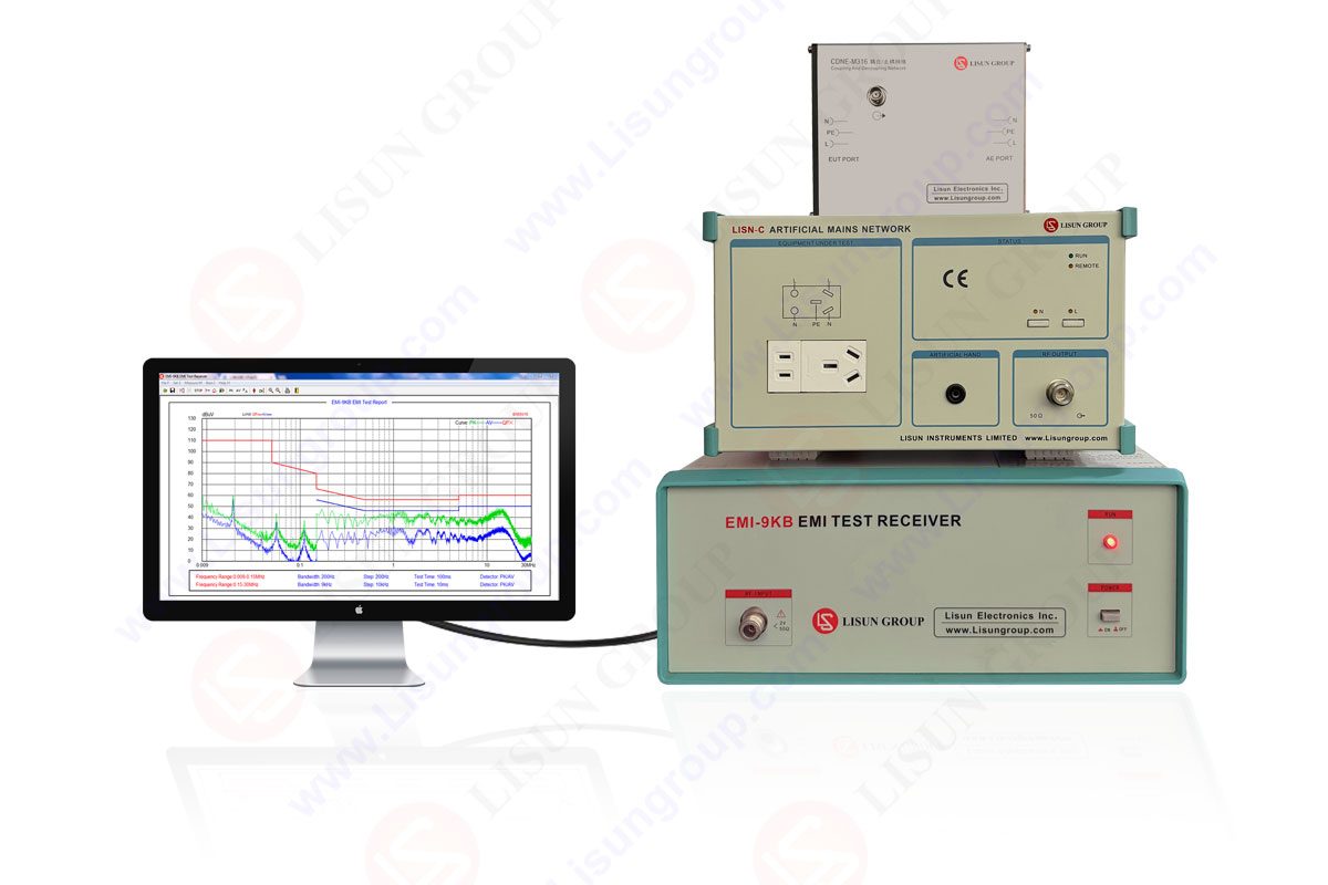
Traditionally, setting up a complete EMI test environment involved numerous discrete instruments (receiver, LISN, antennas, turntable, chamber, etc.), making the system complex and cumbersome to calibrate and maintain. The trend in modern EMC instruments is toward providing highly integrated, automated test systems, such as the LISUN EMI-9K series EMI Receiver Test System.
This system centers around a high-performance EMI receiver, pre-integrated or bundled with standard-required components like LISNs, attenuators, isolation transformers, and control software. Its design essence lies in:
• Unified Operation Platform: Specialized software (supporting Windows) controls the entire test process, including frequency scanning, detector switching, limit line comparison, data logging, and report generation, significantly improving test efficiency and consistency.
• Fully Enclosed Shielded Design: The system employs a fully enclosed structure with excellent shielding effectiveness, fundamentally solving mutual interference issues between internal units. This ensures accurate, stable background noise and test results even in ordinary laboratories.
• Comprehensive Built-in Standards: The receiver comes pre-loaded with limit lines and test requirements from mainstream EMC standards (e.g., CISPR series, EN series, GB series), allowing users to quickly invoke them and simplify setup.
• Powerful Diagnostic Functions: Beyond pass/fail judgment, the system’s high-resolution spectrum analysis function can pinpoint the exact frequency of interference. Combined with optional accessories like near-field probes, it helps R&D engineers quickly locate interference sources at the PCB or module level, aiding in product design optimization.
| Key Parameter / LISUN Model | EMI-9KC | EMI-9KB | Technical Implication & Application Focus |
|---|---|---|---|
| Frequency Range | 9kHz ~ 1000MHz | 9kHz ~ 300MHz | EMI-9KC offers wider coverage, suitable for IT/multimedia devices requiring testing up to 1GHz (CISPR 32). EMI-9KB focuses on low frequencies up to 300MHz, meeting the needs of most household appliances, lighting (CISPR 14-1, 15), and conducted disturbance tests. |
| System Configuration | Receiver, LISN, CDNE, Isolation Transformer, etc. | Receiver, LISN, Isolation Transformer, etc. | EMI-9KC offers a more comprehensive configuration, including a CDNE for asymmetric voltage measurement. Both form a complete foundation for conducted testing. |
| Detection Modes | Peak (PK), Quasi-Peak (QP), Average (AV) | Peak (PK), Quasi-Peak (QP), Average (AV) | Fully compliant with CISPR 16-1-1. The Quasi-Peak detector objectively assesses the actual impact of interference on auditory and visual equipment. |
| Noise Floor | ≤10dBμV (30MHz~1000MHz) | Meets CISPR 16-1-1 requirements | Extremely low self-noise ensures high sensitivity for accurately measuring weak interference signals and avoiding missed detections. |
| Pulse Response Accuracy | ±1dB (Pulse Repetition Frequency ≥20Hz) | ±1.8dB (Pulse Repetition Frequency ≥20Hz) | High pulse response accuracy ensures reliable measurement of transient, pulse-type interference (e.g., switching noise, spark interference) from the EUT. |
| Preselector | Two-stage programmable automatic tracking preselector (30MHz-1GHz) | Not Applicable | The preselector effectively suppresses out-of-band interference and image frequencies, preventing receiver overload and improving measurement dynamic range and accuracy. It is a key component for high-frequency radiated testing. |
| Typical Applicable Standards | CISPR 32, EN 55032, FCC Part 15, etc. | CISPR 14-1, CISPR 15, EN 55014-1, EN 55015, GB 4343.1, GB 17743, etc. | Different models are optimized for different product family standards. Users can select the most suitable system based on their product type (IT equipment vs. appliances/lighting). |
5. Typical Industry Application Scenarios
• Information Technology & Multimedia Equipment: Conducted and radiated disturbance testing for laptops, servers, monitors, etc., ensuring compliance with GB 9254.1 / CISPR 32 and maintaining a clean electromagnetic environment in data centers.
• Household Appliances & Power Tools: Testing switch-mode power supply noise and motor spark interference from products like refrigerators, washing machines, and electric drills. Compliance assessment according to GB 4343.1 / CISPR 14-1 prevents interference with domestic radio reception equipment.
• LED Lighting Equipment: Evaluating the conducted emissions of LED drivers and the overall radiated emissions of luminaires. Testing according to GB 17743 / CISPR 15 ensures they do not affect the wireless communication reliability of smart home systems.
• Third-Party Testing & Certification Laboratories: Serving as EMC instruments for organizations like SGS and TÜV, issuing authoritative EMC test reports for companies based on international standards. Supports certifications like CE, FCC, CCC, facilitating global market access for products.
6. Conclusion
EMC instruments, particularly integrated EMI Receiver Test Systems, have become an indispensable bridge connecting product electrical design with global market compliance. From the precise measurement of conducted disturbances to the systematic assessment of radiated disturbances, a set of reliable, accurate, and efficient EMC instruments can not only objectively determine if a product meets mandatory standards but also provide deep diagnostic insights and optimization guidance during the R&D phase. The integrated solutions represented by the LISUN EMI-9K series, by combining complex standard requirements, precise measurement technology, and intelligent operational workflows, significantly lower the technical barriers and time costs associated with EMC testing. They empower manufacturers, R&D centers, and testing institutions to collectively build a more harmonious and reliable electromagnetic environment.

LISUN’s Motor-Operated Tool | Power Tool Testing solutions strictly comply with a range of core international standards, providing full support for safety and electromagnetic compatibility (EMC)...

LISUN’s transformer test solutions meet IEC 61558-1, IEC 60076-1, IEC 62041 standards. Covering safety, performance, EMC tests, ensuring transformers comply with global requirements.

LISUN’s household and appliance switch testing solutions meet IEC 60669, IEC 61058, IEC 62271 standards. Covering electrical, mechanical & EMC tests for global compliance.

For the CFL design and manufactory, LISUN can supply a full quality control test solution, including photometric, colorimetric, electricity, flicker, IES candela distribution, surge test, electrical...

 中文简体
中文简体