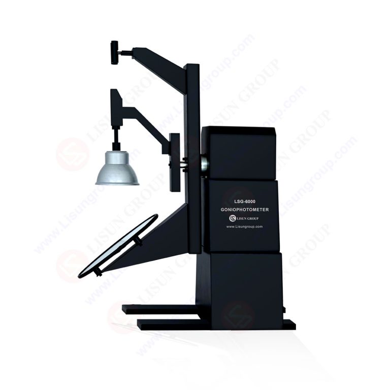
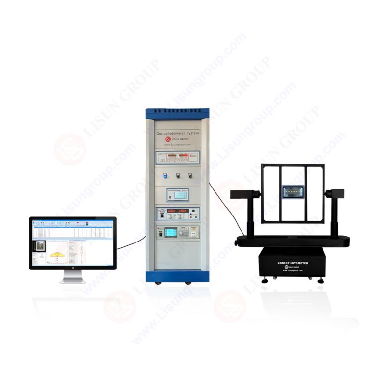
LM-79 Moving Detector Goniophotometer (Mirror Type C)
LSG-6000
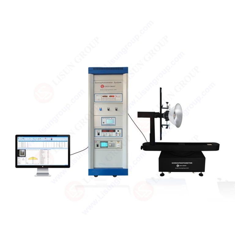
High Precision Rotation Luminaire Goniophotometer
LSG-1890B
High Precision Rotation Luminaire Goniospectroradiometer
LSG-1890BCCD
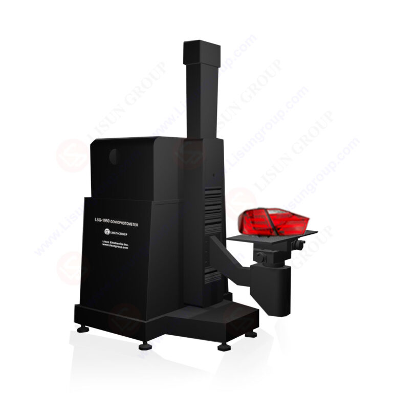
Goniophotometer for Automotive and Signal Lamps
LSG-1950
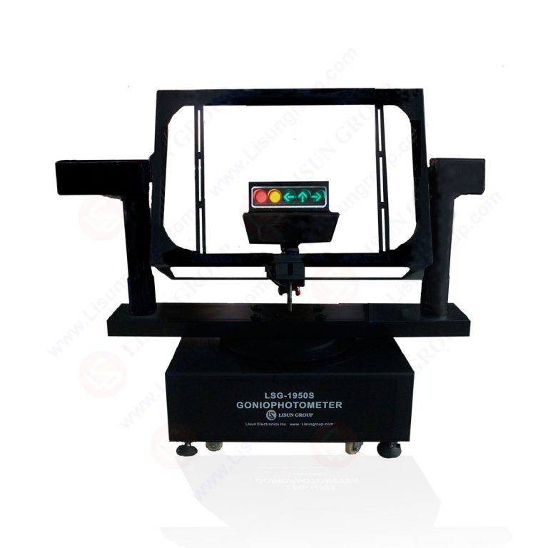
Goniophotometer for Traffic Signal Lamps
LSG-1950S
Compact Goniophotometer
LSG-1200A
Near Field Moving Detector Goniophotometer
LSG-1900B
Select an organization
to browse standards
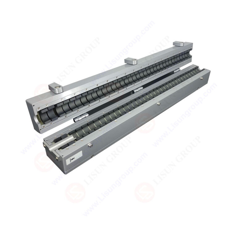

Product No: AB-CLP
The AB-CLP power absorption clamp consists of three core parts: a current transformer, a clamp-on ferrite absorber, and a ferrite tube absorber. It can be connected to LISUN EMI-9K series receivers and other brand receivers via an N-type interface. Through the coordinated action of these components, it achieves the sampling, absorption, and measurement of electromagnetic interference power, accurately capturing interference signals from the tested conductor. It is widely applicable to EMC compliance testing in industries such as home appliances, power tools, and electronic components.
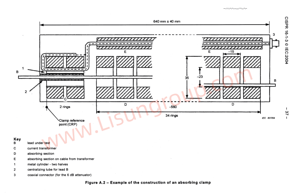
Construction of AB-CLP Power Absorption Clamp
Standards:
| Standards No. | Standards Name |
| CISPR 16-1-3:2020 | Specification for radio disturbance and immunity measuring apparatus and methods – Part 1-3: Radio disturbance and immunity measuring apparatus – Ancillary equipment – Disturbance power |
| CISPR 16-2-2:2013 | Methods of measurement of radio disturbance characteristics – Part 2-2: Measurement of disturbance power |
| VDE 8079 / CISPR 25:2021 | Methods of measurement and limits for radio disturbance characteristics for the protection of receivers on board vehicles |
| CISPR 12:2025 | Vehicles, boats and devices with internal combustion engines or traction batteries – Radio disturbance characteristics – Limits and methods of measurement for the protection of off-board receivers |
| DIN 47250 | Measurement of shielding dimensions of coaxial cables between 30MHz and 1000MHz for high-frequency cables and wires |
| EN 50083-2:2012 | Cable networks for television signals, sound signals and interactive services – Part 2: Electromagnetic compatibility of equipment |
| GB/T 6113.103-2021 | 无线电骚扰和抗扰度测量设备和测量方法规范 第 1-3 部分:无线电骚扰和抗扰度测量设备 辅助设备 骚扰功率 |
| GB/T 6113.202-2021 | 无线电骚扰和抗扰度测量设备和测量方法规范 第 2-2 部分:无线电骚扰和抗扰度测量方法 骚扰功率测量 |
| GB/T 12269-1990 | 射频电缆 — 第 1 部分:一般要求及测量方法 |
Specifications:
| Frequency Fange | 30MHz~1000MHz |
| Output Impedance | 50Ω |
| Permissible Cable Diamete | ≤20mm |
| signal Connector | N type |
| Absorbing Clamp Insertion Loss A | 13dB~21dB |
| Absorption Clamp Factor CF (correction value K) | -4dB~4dB |
| Decoupling Factor DF | ≥21dB |
| Decoupling Factor DR | ≥30dB |
| External Dimensions | 640mm*109mm*100mm(L*W*H) |
| Equipment Weight | 5KG |
| Third-party Calibration Report (optional) | AB-CLP Power Absorption Clamp ISO17025 CNAS Calibration Certificate Sample |
Brief Operating Procedures:
The AB-CLP power absorption clamp must be used in conjunction with a LISUN EMI-9K series receiver or other brand receivers. The entire test must comply with CISPR16-2-2/GB6113.202 standards. The steps are as follows:
1. Pre-test Preparation: Read the absorption clamp factor CF (correction value K) from the accompanying correction factor table and input it into the EMI receiver. If the coaxial cable insertion loss is high, add it to the K value. Turn on the EMI receiver and allow it to warm up for 10 minutes until stable.
2. Test System Setup: Place the absorbing clamp on a 0.8-meter-high insulated slide rail. Connect the output end to the receiver via a 6dB attenuator and a 50Ω coaxial cable. Place a 0.8-meter-high insulated platform on a desktop EUT (refer to Figure 8 of CISPR 16-2-2:2013), and a 0.1-meter-high insulated mat on a floor-standing EUT (refer to Figure 9 of CISPR 16-2-2:2013). Straighten the conductor under test and place it horizontally into the center hole of the absorbing clamp, securing it tightly (bare wire wrapped with insulating tape, minimum conductor length 7.5 meters). Adjust the minimum distance between the slide rail reference point (SRP) and the clamp reference point (CRP) to (10±1) cm.
3. Formal Test: Turn on the EUT power to ensure normal operation. Move the absorbing clamp along the slide rail and read the maximum value from the receiver at each test frequency as the test result, completing the full-band test.
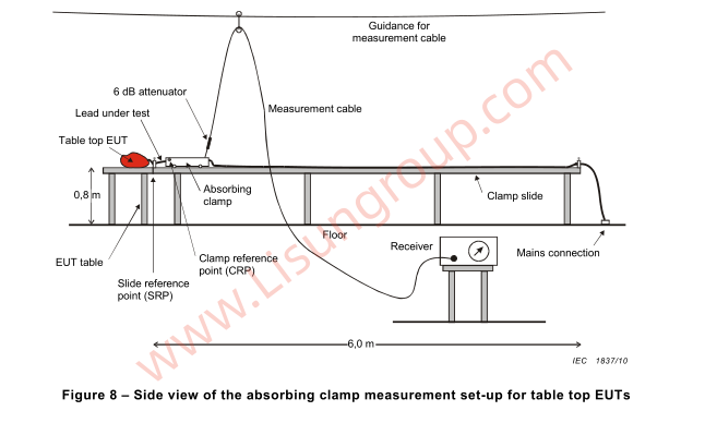
Side view of the absorption clamp measurement setup of a benchtop EUT
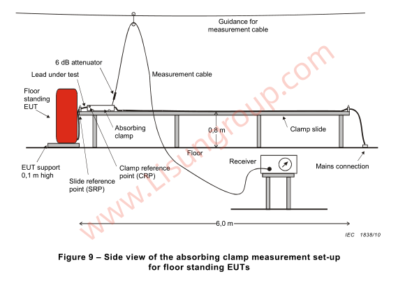
Side view of the absorption clamp measurement setup for a floor-standing EUT

 中文简体
中文简体