
LM-79 Moving Detector Goniophotometer (Mirror Type C)
LSG-6000

High Precision Rotation Luminaire Goniophotometer
LSG-1890B

High Precision Rotation Luminaire Goniospectroradiometer
LSG-1890BCCD

Goniophotometer for Automotive and Signal Lamps
LSG-1950

Goniophotometer for Traffic Signal Lamps
LSG-1950S

Compact Goniophotometer
LSG-1200A

Near Field Moving Detector Goniophotometer
LSG-1900B
Select an organization
to browse standards
Abstract
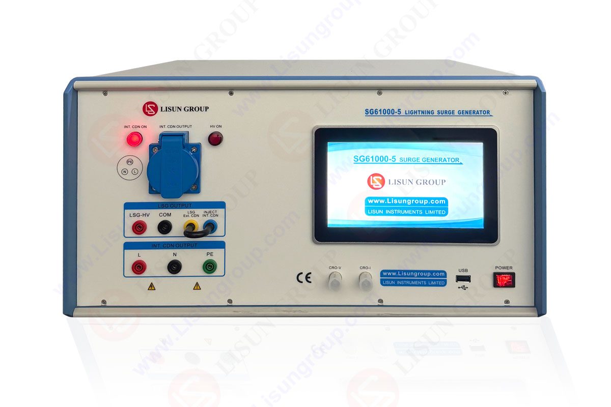
Transient overvoltages and overcurrents caused by lightning strikes and grid switching operations are critical factors threatening the reliability of electrical and electronic equipment. The impulse voltage tester (also referred to as a surge generator) is a core electromagnetic compatibility (EMC) test instrument for simulating such high-energy transient interference and evaluating the withstand capability of equipment ports. This article systematically explains the international standard for surge testing (IEC 61000-4-5), the physical significance of standard combination waveforms (e.g., 1.2/50μs-8/20μs), and the key role of coupling/decoupling networks. Using the LISUN SG61000-5 series Surge Generator as a technical example, the article analyzes how its modular design enables standard waveform output up to 30kV/15kA. Through its integrated oscilloscope and intelligent control, it provides a precise, efficient, and globally standards-compliant immunity verification solution for fields such as new energy and industrial control.
1. Introduction: High-Energy Transient Interference – A Severe Challenge for Equipment Reliability Design
The reliability of electrical and electronic equipment in complex electromagnetic environments depends not only on its own design but also on its ability to withstand high-energy transient disturbances from the power grid. Surge impulses generated by direct/induced lightning strikes and the switching of large loads can inject transient overvoltages and overcurrents far exceeding the equipment’s rated operating range within microseconds, leading to component failure, data loss, or system crashes. Therefore, actively and standardly replicating such interference in a controlled laboratory environment using an impulse voltage tester has become an essential step in evaluating a device’s electromagnetic immunity and meeting mandatory international EMC regulations. The core value of this instrument lies in its ability to precisely quantify a device’s surge withstand threshold based on scientific standards, providing critical data support for robust product design and market access.
2. Surge Immunity Testing: Standard Framework and Core Technical Principles
2.1 Standard Framework and Test Levels
IEC 61000-4-5 (adopted identically in China as GB/T 17626.5) is the authoritative international standard for surge immunity testing. It establishes a complete system covering test waveforms, equipment performance, test setups, and severity levels. Test severity levels (e.g., Level 1 to Level 4) are selected based on the intended installation environment of the equipment (from well-protected indoor to harsh industrial sites). Surge stress must be applied separately to the equipment’s power ports and signal/communication ports.
2.2 Standard Combination Waves and Their Physical Significance
An impulse voltage tester does not generate a simple high-voltage pulse but produces standardized “voltage-current combination waves” to simulate the characteristics of real surges acting on different load impedances. The standards primarily define two key waveform pairs:
• 1.2/50μs – 8/20μs Combination Wave: Used for power port testing. Here, 1.2/50μs (wavefront time 1.2μs, time to half-value 50μs) is the open-circuit voltage waveform; 8/20μs (wavefront time 8μs, time to half-value 20μs) is the short-circuit current waveform. This combination simulates typical interference from lightning induction into low-voltage power distribution systems.
• 10/700μs – 5/320μs Combination Wave: Primarily used for communication port testing. Its open-circuit voltage wave (10/700μs) and short-circuit current wave (5/320μs) have a longer duration, simulating scenarios where lightning energy couples into equipment via long-distance communication lines.
2.3 The Critical Role of Coupling/Decoupling Networks
The Coupling/Decoupling Network (CDN) is an indispensable component for test implementation. Its main functions include: • coupling the surge pulse to the specified port of the Equipment Under Test (EUT); • preventing surge energy from flowing back into the public power supply network or affecting other parallel-connected equipment; • and ensuring consistent stress magnitude and waveform for each test, guaranteeing test repeatability and comparability.

| Model | Open-Circuit Voltage Wave | Short-Circuit Current Wave | Output Voltage Range | Output Current Range | Output Impedance | Core Features |
|---|---|---|---|---|---|---|
| SG61000-5 | 1.2/50μs ±20% | 8/20μs ±20% | 0 ~ 6 kV ±5% | 0 ~ 3 kA ±5% | 2Ω, 12Ω | Base model, integrated oscilloscope |
| SG61000-5H-SP | 1.2/50μs ±20% | 8/20μs ±20% | 0 ~ 10 kV ±5% | 0 ~ 5 kA ±5% | 2Ω, 12Ω, 500Ω | High-performance single-phase model, multi-impedance |
| SG61000-5H30-SP* | 1.2/50μs ±20% | 8/20μs ±20% | 0 ~ 30 kV ±5% | 0 ~ 15 kA ±5% | 2Ω, 12Ω, 500Ω | Ultra-high output capability model |
| SG61000-5C | 10/700μs ±20% | 5/320μs ±20% | 0 ~ 6 kV ±5% | 0 ~ 150 A ±5% | 15Ω, 40Ω | Communication line surge test model |
3. Technical Integration and Innovation of the SG61000-5 Series Surge Generators
The LISUN SG61000-5 series represents the trend of modern Surge Generators towards high integration, intelligence, and operational simplicity.
3.1 Fully Automated Waveform Generation and Precise Control
This series employs a modular design, covering a wide range of needs from basic compliance testing to high-intensity validation. Its core capability lies in accurately generating and controlling the combination waves specified by the standards, with voltage and current output accuracy of ±5% and waveform parameter tolerances strictly controlled within ±20%, ensuring the authority of the tests.
3.2 Integrated Measurement and Visual Operation
A significant technological innovation is the integration of voltage/current attenuator probes and an electronic oscilloscope. Users can directly and实时 observe the output surge waveform on the device’s own LCD touchscreen without the need for an external, bulky oscilloscope, instantly verifying whether waveform parameters comply with standards (e.g., 1.2/50μs, 8/20μs). This “what-you-see-is-what-you-get” design greatly simplifies the testing process, reducing operational complexity and the risk of configuration errors.
3.3 Flexible Coupling Solutions and Safety Assurance
The equipment supports various built-in and external coupling/decoupling networks, adapting to the testing needs of single-phase, three-phase power supplies, and various communication lines. Combined with optional surge test protection devices (e.g., PD-E01), dedicated test tables, and isolation transformers, a complete and safe test environment can be established, effectively protecting operators and auxiliary equipment.
| Parameter Category | Technical Specification | Performance Significance |
|---|---|---|
| Open-Circuit Voltage Wave | 1.2/50μs ±20% | Simulates lightning-induced voltage in low-voltage distribution systems |
| Short-Circuit Current Wave | 8/20μs ±20% | Simulates lightning-induced current in low-voltage distribution systems |
| Output Voltage Range | 0 ~ 30 kV ±5% | Provides extremely high voltage output for severe-level testing |
| Output Current Range | 0 ~ 15 kA ±5% | Provides extremely high current output to simulate high-energy impacts |
| Output Impedance | 2Ω, 12Ω, 500Ω | Matches source impedance requirements for different test ports |
| Output Accuracy | ±5% | Ensures accuracy and repeatability of applied test stress |
4. Core Application Scenarios and Selection Guidance
The impulse voltage tester finds applications in multiple fields with extremely high reliability requirements:
• New Energy Industry: Testing the withstand capability of photovoltaic inverters, energy storage converters, and charging piles against grid-side surge impacts to ensure grid connection safety.
• Industrial Automation: Evaluating the reliability of PLCs, servo drives, and industrial power supplies in complex industrial grid environments to prevent production interruptions.
• Information & Communication Technology: Verifying the surge protection performance of communication ports in switches, routers, and base station equipment to ensure network infrastructure stability.
• Consumer Electronics & Appliances: Meeting mandatory surge immunity testing requirements for power ports in international safety certifications (e.g., CE, UL).
Selection Advice: Users should select a model with corresponding output voltage/current capability and waveform combination based on the industry standards applicable to the Equipment Under Test (e.g., test levels specified in IEC 61000-4-5), maximum operating voltage, and the type of port requiring testing (power line/communication line). For R&D and applications in harsh environments, models with greater output headroom (e.g., the SG61000-5H series) should be considered.
5. Conclusion
In summary, the impulse voltage tester is a key instrument bridging theoretical standards and engineering practice, transforming the abstract “surge threat” into a standardized test stress that can be precisely measured and repeatedly applied. Modern test solutions, represented by the LISUN SG61000-5 series, through their high-precision waveform generation, integrated measurement, and intelligent control, not only significantly improve test efficiency and accuracy but also make in-depth evaluation and optimization of a device’s transient immunity design possible. In today’s era of deep integration between electrification and digitization, investing in and effectively utilizing such professional testing tools is a crucial technical guarantee for ensuring product competitiveness in the global market and earning a lasting reputation for reliability.

LISUN’s Motor-Operated Tool | Power Tool Testing solutions strictly comply with a range of core international standards, providing full support for safety and electromagnetic compatibility (EMC)...

LISUN’s electric toy testing solutions cover IEC 62115, EN 71-1, ASTM F963 standards. Including electrical, mechanical, flammability tests to ensure toy safety compliance globally.

LISUN’s transformer test solutions meet IEC 61558-1, IEC 60076-1, IEC 62041 standards. Covering safety, performance, EMC tests, ensuring transformers comply with global requirements.

LISUN’s energy meter testing solutions align with IEC 62052-11, IEC 62053 series standards. Covering safety, electrical, environmental, and EMC tests, we help manufacturers meet global compliance...

LISUN’s household and appliance switch testing solutions meet IEC 60669, IEC 61058, IEC 62271 standards. Covering electrical, mechanical & EMC tests for global compliance.
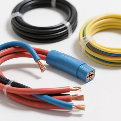
LISUN’s cable and wire test solutions meet IEC 60245-1, IEC 60227-1, IEC 60502-1 and IEC 60189 standards, covering electrical, mechanical, and safety tests for global compliance.
LISUN has all equipment according to the IEC60669 measurement, including environmental chamber, IP code waterproof dustproof test, switch lift test, etc.

Lisun can supply full test solutions for fluorescent lamp, including integrating sphere system, goniophotometer system, EMI EMC test, electronic ballast tester, electrical safety test, etc.

For the CFL design and manufactory, LISUN can supply a full quality control test solution, including photometric, colorimetric, electricity, flicker, IES candela distribution, surge test, electrical...

LISUN’s LED driver test solutions cover lab testing, online testing, EMC/EMI tests, and safety checks, meeting IEC 60335, UL 60335 standards for reliable performance evaluation.

 中文简体
中文简体