
LM-79 Moving Detector Goniophotometer (Mirror Type C)
LSG-6000

High Precision Rotation Luminaire Goniophotometer
LSG-1890B

High Precision Rotation Luminaire Goniospectroradiometer
LSG-1890BCCD

Goniophotometer for Automotive and Signal Lamps
LSG-1950

Goniophotometer for Traffic Signal Lamps
LSG-1950S

Compact Goniophotometer
LSG-1200A

Near Field Moving Detector Goniophotometer
LSG-1900B
Select an organization
to browse standards
Electronic noise that interferes with cable transmissions and decreases signal integrity is known as Electromagnetic Interference or an EMI receiver. Electromagnetic radiation sources, such as motors and machines, are common sources of EMI receiver.
There are two types of EMI receivers. These are conducted interference and radiated interference. The connection of signals on one electrical network to another electrical network over a conductive medium is referred to as conductive interference. The interference source connecting its signal to another electrical network over space is referred to as radiated interference.

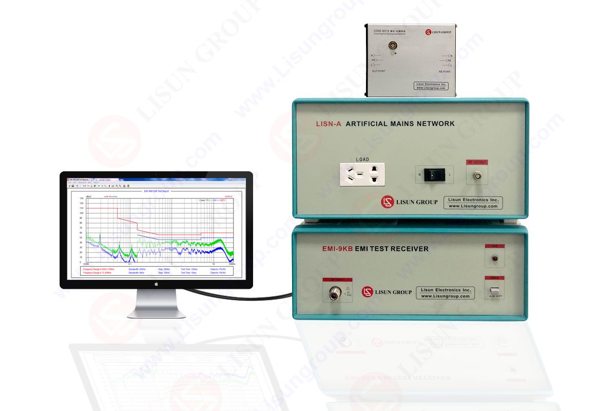
EMI Test Receiver
For EMI radiation conduction or conducted emissions testing, the EMI-9KB is an automatic EMI receiver system. The EMI-9KB EMI receiver is made up of a full-closure construction and a high-conductivity material with a high shielding effect. The international standards CISPR15:2018, CISPR16-1, GB17743, FCC, EN55015, and EN55022 are all fully met by the EMI Test System EMI-9KB.
Radiated emissions testing entails determining the electromagnetic field strength of accidentally created emissions from your product. All digital circuit produces emissions due to the switching voltages and currents; the only question is how large the emissions are and if they meet the emission restrictions.

Electromagnetic waves do not radiate in a spherical pattern from your goods. Both the direct signal from the EUT and a bounce off the ground are picked up by the receiving antenna. The ground is covered with an electromagnetically reflective surface (aluminum, steel, wire mesh, etc.) to improve measurement accuracy, and this ground plane must be somewhat flat.
The radiated emissions test is one of the most common EMC test types. Radiated emissions testing is the measurement of the electromagnetic field of emissions produced by the equipment under test inadvertently. Several antennas may be necessary to cover the complete frequency range of interest. The following are the figures for the field strength of radiated emissions.
Electromagnetic energy is generated by your gadget, and some of it is passed onto the power supply wire. Test labs measure these emissions, which are typically between 150 kHz and 30 MHz, and verify that they meet with defined limitations in order to limit the amount of interference your device can couple back onto a power source. This ensures that the local power supply remains generally ‘clean,’ and that your gadget does not harm nearby devices.
Your product is on a table, whereas the line impedance stabilization network are either on the ground or remains floor standing if the equipment is large. A spectrum analyzer is directly connected to a LISUN’s RF connector or via a transient limiter to prevent damage from voltage spikes.
• AB-CLP Absorbing Clamp can be used to test out Home Applications & motor tools
• LISUN VVLA-30M Three Loop Antenna can be used to test 9k-30MHz Radiation
• LISUN SDR-2000B Magnetic Shielding Cabinet for the EMI Receiver System
• LISUN LSP-500VARC/LSP-1KVARC Pure Sine Wave AC Power Source for EUT
For evaluating radiated emissions from electronic products, there are two main types of test sites. These test sites are:
1. Open Area Test Site (OATS)
2. Semi Anechoic Chamber
The purpose of these test sites is to correctly measure your product’s emissions and guarantee that they are within acceptable limits.
A radiated emissions test can be failed in a virtually infinite number of ways. Here’s a rundown of some of the most common design issues:
• Noise on the cabling
• High PDN impedance
• Poor board grounding
• Non-optimized layer stack
• Large current loops
• Poor signal integrity
• Ineffective board decoupling
• Poor cable termination
• Segmented ground fills
• Non-compliant auxiliary equipment
• Choosing wrong class of power supply
• Poor decoupling capacitor and capacitor routing
Devices that connect to an AC power supply are typically subjected to conducted emissions testing. That is irrelevant of whether you’re utilizing a pre-certified AC-DC power supply adaptor. Devices that operate on a DC power supply are likewise subject to restrictions in some standards.
Devices that fail emissions testing are extremely widespread. Even if your equipment is powered by an external AC-DC power adapter that has been pre-certified, it isn’t guaranteed to pass. This is due to a number of factors which include
• There’s a chance the power source isn’t compliant.
It’s not uncommon to see power supplies that appear to be compliant but are actually non-compliant when re-tested. This could be due to a variety of factors, including batch to batch differences, errors in the original testing, or changes in technology after the initial testing.
• A DC load was used to test the original power adapter.
LISUN have their power supply adapters evaluated typically do so with a DC load connected to the output, with the value set to match the highest rated current draw.Because your equipment will draw both DC and AC/RF currents, the adapter’s emissions profile will be different from when it was first tested.
Lisun Instruments Limited was found by LISUN GROUP in 2003. LISUN quality system has been strictly certified by ISO9001:2015. As a CIE Membership, LISUN products are designed based on CIE, IEC and other international or national standards. All products passed CE certificate and authenticated by the third party lab.
Our main products are Goniophotometer, Integrating Sphere, Spectroradiometer, Surge Generator, ESD Simulator Guns, EMI Receiver, EMC Test Equipment, Electrical Safety Tester, Environmental Chamber, Temperature Chamber, Climate Chamber, Thermal Chamber, Salt Spray Test, Dust Test Chamber, Waterproof Test, RoHS Test (EDXRF), Glow Wire Test and Needle Flame Test.
Please feel free to contact us if you need any support.
Tech Dep: Service@Lisungroup.com, Cell/WhatsApp:+8615317907381
Sales Dep: Sales@Lisungroup.com, Cell/WhatsApp:+8618117273997

LISUN’s Motor-Operated Tool | Power Tool Testing solutions strictly comply with a range of core international standards, providing full support for safety and electromagnetic compatibility (EMC)...

LISUN’s transformer test solutions meet IEC 61558-1, IEC 60076-1, IEC 62041 standards. Covering safety, performance, EMC tests, ensuring transformers comply with global requirements.

LISUN’s household and appliance switch testing solutions meet IEC 60669, IEC 61058, IEC 62271 standards. Covering electrical, mechanical & EMC tests for global compliance.

For the CFL design and manufactory, LISUN can supply a full quality control test solution, including photometric, colorimetric, electricity, flicker, IES candela distribution, surge test, electrical...

 中文简体
中文简体