IS 10322-1:2014 is the Indian national standard corresponding to the general specification and test provisions for all types of luminaires, establishing unified baseline safety, construction and...
The IEC 60320-1:2007 standard specifies general requirements for appliance couplers intended for household and similar general purposes. These couplers are primarily used for connecting electrical appliances...
This International Standard IEC 61643-11:2011 specifies the general requirements for low‑voltage surge protective devices (SPDs) connected to low‑voltage power distribution systems. It defines terms, classification, operating...
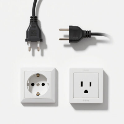
AS/NZS 3112:2025 is the harmonized Australian and New Zealand Standard for AC power plugs and socket-outlets, applicable to devices rated up to 500 V and 32...
UL 62275:2025 sets strict safety and performance standards for electrical installation cable ties, classifying them into Type 2/21/2S/21S with tiered testing requirements. It mandates mechanical strength...
UL 746C:2001, issued by Underwriters Laboratories (UL) as the fifth edition on November 29, 2001 (ANSI-approved September 23, 2002), is a safety standard that establishes evaluation...
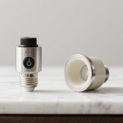
IS 16102 (Part 1): 2026 is the latest Indian standard specifying safety requirements for self‑ballasted LED lamps used for general lighting services. Compared with the previous...
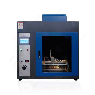
The standard EN 60745-1:2003, “Hand-held motor-operated electric tools — Safety — Part 1: General requirements,” outlines the safety specifications for hand-held electric tools powered by motors....
As a revised edition released in 2023, IEC 61869-1:2023 supersedes the 2007 version of the same standard as well as IEC 61869-6:2016, updating technical content to...
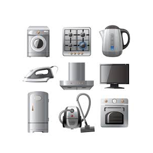
IEC 60335-2-6:2024 is a safety standard focusing on stationary electric cooking appliances for household and similar use, including cooking ranges, hobs (e.g., induction cooktops), ovens (pyrolytic,...
IEC 62560:2015 is a universal safety standard for self-ballasted LED lamps used in general lighting, with a rated voltage over 50 V (e.g., common screw/bayonet LED...
IEC 60968:2015 is an international safety standard governing self-ballasted fluorescent lamps (SBFLs) for general lighting applications. It applies to lamps with a rated voltage of 50V...
IEC 60730-1:2010 defines general safety and performance requirements for automatic electrical controls used in or with household and similar equipment, encompassing energy sources like electricity, gas,...
IS 1293:2019 is India’s national standard (by BIS) for household and similar-purpose plugs and socket-outlets with rated voltage ≤250V and rated current ≤16A. Its primary aim...
IS 3854:2023 is India’s national standard (by BIS) for domestic and similar-purpose switches. It applies to manual AC switches (up to 250V, 20A) used in homes,...
IEC 60838-1:2020 is an international standard developed by the International Electrotechnical Commission (IEC) that specifies general requirements and corresponding test methods for miscellaneous lampholders. Released in...
In addition, IEC 60400:2004 also details the specific test methods. These testing procedures are utilized to verify the compliance of lampholders and starter – holders with...
IEC 60238:2020 focuses on key performance and safety criteria, such as electrical insulation resistance, contact conductivity (typically requiring corrosion-resistant materials like brass for current-carrying parts), and...
IEC 62841-1:2014 “Electric Motor-Operated Hand-Held, Transportable Tools and Lawn and Garden Machinery – Safety – Part 1: General Requirements” establishes foundational safety guidelines for handheld and...
The IEC 61029-1:1990 standard, titled “Safety of transportable motor-operated electric tools – PART 1: General requirements”, focuses on establishing comprehensive safety norms for portable electric tools....
IEC 60745-1:2006 is a pivotal standard that details the safety requirements for hand-held motor-operated electric tools. Applicable to tools with single-phase AC/DC voltage up to 250V...
IS 15644:2006 is an Indian standard that focuses on the safety of electric toys. It applies to toys with at least one electrical function, including constructional...
IEC 62115:2017 Electric toys—Safety is an international standard established by the International Electrotechnical Commission (IEC), specifying safety requirements for electric toys designed or intended for use...
IEC 61558-1:2017 is a safety standard developed by the International Electrotechnical Commission (IEC) for transformers, reactors, power supply units, and their combinations. It applies to various...
IEC 62052 – 31:2024 is a standard about electricity metering equipment formulated by the International Electrotechnical Commission (IEC). It specifies general safety requirements and associated tests,...
IEC 60838-1:2020, titled “Miscellaneous Lampholders – Part 1: General Requirements and Tests,” specifies the general requirements and testing methods for various types of lampholders intended for...
IEC 60065:2014 outlines safety requirements for audio, video, and similar electronic devices, aiming to protect users from electrical, mechanical, and thermal hazards.
IEC 62052-11:2003 specifies general requirements, tests, and test conditions for AC electricity metering equipment. It covers aspects such as functionality, mechanical structure, electrical characteristics, and marking...
IEC 62640:2011 specifies requirements for residual current devices (RCDs) with or without overcurrent protection intended for household and similar applications. These devices are designed to provide...
IEC 61347-1:2024 specifies the general safety requirements for controlgear used with electric light sources, including fluorescent lamps, LED modules, discharge lamps, and other lighting technologies.
This standard IEC 61195:2014 applies to double-capped fluorescent lamps, including general lighting and high-efficiency types. It sets requirements for mechanical structure, electrical performance, and protection against...
This standard IEC 60598-2-10:2003 applies to portable luminaires designed for children’s use, such as bedside lamps and toy lamps. It requires that the luminaire structure avoids...
IEC 61058-1:2016 is available as IEC 61058-1:2016 RLV which contains the International Standard and its Redline version, showing all changes of the technical content compared to...
For switches provided with screwless terminals, the rated current is limited to 16 A. This fourth edition cancels and replaces the third edition published in 1998,...
IEC 60898-1:2019 specifies requirements for circuit breakers intended for overcurrent protection in household and similar installations. These devices are designed for alternating current (AC) circuits with...
The IEC 62986:2017 standard specifies the technical requirements, design features, and test methods for plugs, socket-outlets, and couplers with arcuate contacts.
The IEC 61386-1:2017 standard provides general requirements for conduit systems used in cable management. It outlines the technical specifications and performance criteria for conduit systems, including...
This part of IEC 62613-1:2019 applies to accessories with • three phases and earth with pilot contacts, • one pole for neutral.
The IEC 62052-11 standard specifies the general requirements, testing methodologies, and test conditions for electricity metering equipment used in alternating current (AC) systems. It covers essential...
The IEC 62560:2015 standard specifies safety requirements for self-ballasted LED lamps intended for general lighting purposes, with voltages greater than 50 V and up to 250...
This part of IEC 60998 applies to connecting devices as separate entities for the connection of two or more electrical copper conductors (complying with IEC 60228...
This part of IEC 62868-1: 2020 provides a set of general safety requirements and tests of OLED light sources which are applicable to general indoor lightings.
This Standard UL 1598: 2012 is issued jointly by the Association of Standardization and Certification (ANCE), the Canadian Standards Association (CSA),and Underwriters Laboratories Inc. (UL).
The IEC 62031:2008 standard outlines essential safety and general requirements for light-emitting diode (LED) modules utilized in general lighting applications. It provides the framework for ensuring...
The IEC 60335-2-40:2022 standard specifies the safety requirements for electrical heat pumps, air-conditioners, and dehumidifiers used in household and similar applications. This part of the IEC...
The standard covers safety requirements for electrical appliances that operate with a voltage up to 250V for single-phase appliances and up to 480V for other appliances....
The purpose of this document IEC 60947-1:2020 is to harmonize as far as practicable all rules and requirements of a general nature applicable to low-voltage switchgear...
International Standard IEC 60245-1: 2003 has been prepared by IEC technical committee 20:Electric cables.
The IEC 61439-1: 2011 standard, titled “Low-voltage switchgear and controlgear assemblies – Part 1: General rules”, specifies the general requirements for low-voltage switchgear and controlgear assemblies....
Standard IS 15111:2002( Part 1 ) was adopted by the Bureau of Indian Standards, after the draft finalized by the Electric Lamps and Their Auxiliaries Sectional...
IS 2418-1:2018 Indian Standard (Part 1) (Second Revision) was adopted by the Bureau of Indian Standards, after the draft finalized by the Lamps and Related Equipments...
The standard IS 16614: Part 1: 2018 – Double-Capped LED Linear Lamps – Part 1: Safety Specification outlines the safety requirements for double-capped LED linear lamps...
This Standard also applies to boxes for the installation of devices whose casing is an integral part of the same. Requirements for built-in boxes and boxes...
The BIS IS 16103 (Part 1): 2012 standard, issued by the Bureau of Indian Standards (BIS), covers the specifications for LED modules for general lighting purposes
The BS 1363 series provides essential requirements for the safety, construction, dimensional accuracy, electrical and mechanical testing, and markings for the UK national electrical power plug...
IEC 60335-1:2020 deals with the safety of electrical appliances for household and similar purposes, their rated voltage being not more than 250 V for single-phase appliances...
IEC 60598-1:2020 is available as IEC 60598-1:2020 RLV which contains the International Standard and its Redline version, showing all changes of the technical content compared to...
This Documents(EN 60670-1:2021) consists of the text of IEC 60670-1:2015 prepared by SC 23B “Plugs, socket-outlets and switches” of IEC/TC 23″ Electrical accessories”.
This part of IEC 60884 applies to plugs and fixed or portable socket-outlets for AC only, with or without earthing contact, with a rated voltage greater...
The following principles have been adopted by technical committe 108 in the development of this standard.These principles do not cover performance or functional characteristics of equipment....
IEC 60335-2-5Household and similar electrical appliances – Safety – Part 2-5: Particular requirements for dishwashers need to use LISUN goniophotometer, integrating sphere and spectroradiometer system to...
IEC 60335-2-4Household and similar electrical appliances – Safety – Part 2-4: Particular requirements for spin extractors need to use LISUN goniophotometer, integrating sphere and spectroradiometer system...
IEC 60335-2-7Household and similar electrical appliances – Safety – Part 2-7: Particular requirements for washing machines need to use LISUN goniophotometer, integrating sphere and spectroradiometer system...
IEC 60335-2-8Household and similar electrical appliances – Safety – Part 2-8: Particular requirements for shavers, hair clippers and similar appliances need to use LISUN goniophotometer, integrating...
IEC 60335-2-9Household and similar electrical appliances – Safety – Part 2-9: Particular requirements for grills, toasters and similar portable cooking appliances need to use LISUN goniophotometer,...
IEC 60745-2-1Hand-held motor-operated electric tools- Safety- Part 2-1: Particular requirements for drills and impact drills need to use LISUN goniophotometer, integrating sphere and spectroradiometer system to...
IEC 60745-2-12Hand-held motor-operated electric tools -Safety – Part 2-12: Particular requirements for concrete vibrators need to use LISUN goniophotometer, integrating sphere and spectroradiometer system to test
IEC 60745-2-14Hand-held motor-operated electric tools -Safety – Part 2-14: Particular requirements for planers need to use LISUN goniophotometer, integrating sphere and spectroradiometer system to test
IEC 60745-2-2Hand-held motor-operated electric tools – Safety – Part 2-2: Particular requirements for screwdrivers and impact wrenches need to use LISUN goniophotometer, integrating sphere and spectroradiometer...
IEC 60745-2-3Hand-held motor-operated electric tools-Safety – Part 2-3: Particular requirements for grinders, polishers and disk-type sanders need to use LISUN goniophotometer, integrating sphere and spectroradiometer system...
IEC 60745-2-4Hand-held motor-operated electric tools – Safety – Part 2-4: Particular requirements for sanders and polishers other than disk type need to use LISUN goniophotometer, integrating...
IEC 60745-2-11Hand-held motor-operated electric tools – Safety – Part 2-11: Particular requirements for reciprocating saws (jig and sabre saws) need to use LISUN goniophotometer, integrating sphere...
IEC 60335-2-21Household and similar electrical appliances – Safety – Part 2-21: Particular requirements for storage water heaters need to use LISUN goniophotometer, integrating sphere and spectroradiometer...
IEC 60335-2-10Household and similar electrical appliances – Safety – Part 2-10: Particular requirements for floor treatment machines and wet scrubbing machines need to use LISUN goniophotometer,...
IEC 60335-2-11Household and similar electrical appliances – Safety – Part 2-11: Particular requirements for tumble dryers need to use LISUN goniophotometer, integrating sphere and spectroradiometer system...
IEC 60335-2-12Household and similar electrical appliances – Safety – Part 2-12: Particular requirements for warming plates and similar appliances need to use LISUN goniophotometer, integrating sphere...
IEC 60335-2-13Household and similar electrical appliances – Safety – Part 2-13: Particular requirements for deep fat fryers, frying pans and similar appliances need to use LISUN...
IEC 60335-2-14Household and similar electrical appliances – Safety – Part 2-14: Particular requirements for kitchen machines need to use LISUN goniophotometer, integrating sphere and spectroradiometer system...
IEC 60335-2-15Household and similar electrical appliances – Safety – Part 2-15: Particular requirements for appliances for heating liquids need to use LISUN goniophotometer, integrating sphere and...
IEC 60335-2-16Household and similar electrical appliances – Safety – Part 2-16: Particular requirements for food waste disposers need to use LISUN goniophotometer, integrating sphere and spectroradiometer...
IEC 60335-2-17Household and similar electrical appliances – Safety – Part 2-17: Particular requirements for blankets, pads, clothing and similar flexible heating appliances need to use LISUN...
IEC 60335-2-2Household and similar electrical appliances – Safety – Part 2-2: Particular requirements for vacuum cleaners and water-suction cleaning appliances need to use LISUN goniophotometer, integrating...
IEC 60335-2-23Household and similar electrical appliances – Safety – Part 2-23: Particular requirements for appliances for skin or hair care need to use LISUN goniophotometer, integrating...
IEC 60335-2-24Household and similar electrical appliances – Safety – Part 2-24: Particular requirements for refrigerating appliances, ice-cream appliances and ice makers need to use LISUN goniophotometer,...
IEC 60335-2-25Household and similar electrical appliances – Safety – Part 2-25: Particular requirements for microwave ovens, including combination microwave ovens need to use LISUN goniophotometer, integrating...
IEC 60335-2-27Household and similar electrical appliances – Safety – Part 2-27: Particular requirements for appliances for skin exposure to optical radiation need to use LISUN goniophotometer,...
IEC 60335-2-29Household and similar electrical appliances – Safety – Part 2-29: Particular requirements for battery chargers need to use LISUN goniophotometer, integrating sphere and spectroradiometer system...
IEC 60335-2-3Household and similar electrical appliances – Safety – Part 2-3: Particular requirements for electric irons need to use LISUN goniophotometer, integrating sphere and spectroradiometer system...
IEC 60335-2-32Household and similar electrical appliances – Safety – Part 2-32: Particular requirements for massage appliances need to use LISUN goniophotometer, integrating sphere and spectroradiometer system...
IEC 60335-2-35Household and similar electrical appliances – Safety – Part 2-35: Particular requirements for instantaneous water heaters need to use LISUN goniophotometer, integrating sphere and spectroradiometer...
IEC 60335-2-26Household and similar electrical appliances – Safety – Part 2-26: Particular requirements for clocks need to use LISUN goniophotometer, integrating sphere and spectroradiometer system to...
IEC 61347-2-13Lamp controlgear – Part 2-13: Particular requirements for d.c. or a.c. supplied electronic controlgear for LED modules need to use LISUN goniophotometer, integrating sphere and...
IEC 60745-2-8Hand-held motor-operated electric tools – Safety – Part 2-8: Particular requirements for shears and nibblers need to use LISUN goniophotometer, integrating sphere and spectroradiometer system...
IEC 60745-2-9Hand-held motor-operated electric tools-Safety- Part 2-9: Particular requirements for tappers need to use LISUN goniophotometer, integrating sphere and spectroradiometer system to test
IEC 60745-2-5Hand-held motor-operated electric tools- Safety- Part 2-5: Particular requirements for circular saws need to use LISUN goniophotometer, integrating sphere and spectroradiometer system to test
IEC 60745-2-6Hand-held motor-operated electric tools-Safety- Part 2-6: Particular requirements for hammers need to use LISUN goniophotometer, integrating sphere and spectroradiometer system to test


 中文简体
中文简体