LM-79 Moving Detector Goniophotometer (Mirror Type C)
LSG-6000

High Precision Rotation Luminaire Goniophotometer
LSG-1890B

High Precision Rotation Luminaire Goniospectroradiometer
LSG-1890BCCD

Goniophotometer for Automotive and Signal Lamps
LSG-1950

Goniophotometer for Traffic Signal Lamps
LSG-1950S

Compact Goniophotometer
LSG-1200A

Near Field Moving Detector Goniophotometer
LSG-1900B
Select an organization
to browse standards
Abstract
In fields such as electrical and electronic products, new energy, and communications, lightning surge interference faced by equipment is a key factor leading to product failures and performance degradation. EMC (Electromagnetic Compatibility) compliance certification is a crucial threshold for products to enter the market. This paper takes the LISUN SG61000-5 Surge Tester Manufacturers as the research object, and based on international and domestic standards such as IEC 61000-4-5 and GB/T 17626.5, systematically expounds the modular design principle, core technical parameters, and testing process of this equipment. It focuses on analyzing its application scenarios in different fields, intuitively presents the equipment performance through constructing a standard waveform and test parameter comparison table, and verifies its practicality in EMC compliance certification with actual test cases. The research shows that the LISUN SG61000-5 Surge Tester Manufacturers, with its wide output range of 0~30KV voltage and 0~15KA current, multi-standard waveform output capability such as 1.2/50μs, and user-friendly design with built-in detection modules, can accurately meet the EMC testing needs of various industries, providing reliable technical support for enterprises to pass product compliance certification.
1. Introduction
With the development of electronic equipment towards high integration and high sensitivity, their tolerance to external electromagnetic interference has become increasingly critical. Lightning surge, as a typical source of electromagnetic interference, may intrude into the internal of equipment through power lines and signal lines, leading to chip burnout, data loss, and even permanent damage to the equipment. To standardize the testing standards for the lightning surge resistance of products, the International Electrotechnical Commission (IEC) has formulated IEC 61000-4-5 Electromagnetic Compatibility (EMC) – Part 4-5: Testing and Measurement Techniques – Surge Immunity Test, and China has simultaneously launched GB/T 17626.5 Electromagnetic Compatibility – Testing and Measurement Techniques – Surge (Impact) Immunity Test. These standards clearly require that products must pass lightning surge tests of specific levels before they can enter the market.
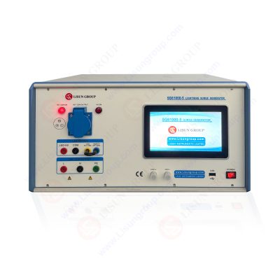
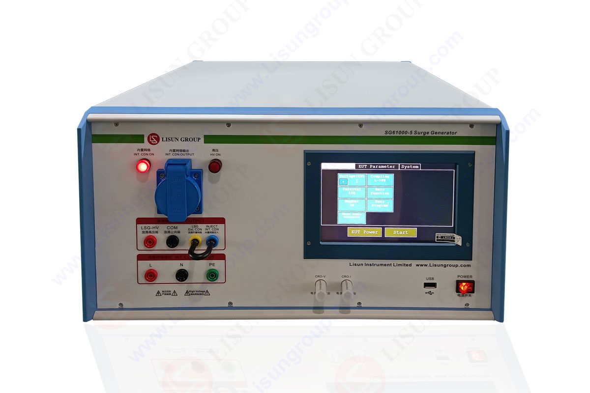
Against this background, professional surge tester manufacturers have become core equipment for enterprises in R&D, production, and third-party testing institutions to conduct EMC compliance testing. As a leading enterprise in the field of electromagnetic compatibility testing equipment, LISUN Group has developed the SG61000-5 Surge Tester Manufacturers, which adopts a modular design, covers a wide range of voltage and current outputs, supports multiple standard waveforms, and has a built-in detection module to simplify the operation process. This paper will comprehensively analyze the value of the LISUN SG61000-5 Surge Tester Manufacturers from the dimensions of equipment design standards, technical performance, and application scenarios, providing practical references for multi-field EMC compliance testing.

Surge Generator SG61000-5
2. Design Standards and Technical Principles of LISUN SG61000-5 Surge Tester Manufacturers
2.1 Core Technical Principles
The LISUN SG61000-5 Surge Tester Manufacturers is based on the “capacitor energy storage discharge” principle, and its core structure consists of a modular high-voltage power supply, an energy storage capacitor bank, a waveform forming network, a built-in detection module (voltage and current attenuator probes + electronic oscilloscope), and a control system. Its working process is as follows:
• Energy Storage: Select the corresponding voltage module according to the test requirements. The high-voltage power supply charges the energy storage capacitor bank, storing electrical energy in the capacitors. The energy storage capacity is determined by the voltage level and capacitor capacity (energy formula: E=0.5CV²);
• Waveform Formation: The energy from the capacitor discharge is converted into a standard waveform through a waveform forming network (composed of resistors, inductors, and capacitors), such as 1.2/50μs (open-circuit voltage) and 8/20μs (short-circuit current). Here, “1.2μs” is the voltage rise time, and “50μs” is the voltage wave half-peak time, ensuring that the waveform parameters meet standard requirements;
• Surge Injection: The standard surge signal is injected into the power line or signal line of the test sample through a coupling/decoupling network to simulate actual lightning surge interference;
• Real-time Detection: The built-in voltage and current attenuator probes collect the surge signal, which is processed by the electronic oscilloscope and displayed in real-time on the LCD touchscreen. The waveform parameters can be observed intuitively without external instruments;
• Result Judgment: After the test, the surge resistance performance of the test sample is judged based on its functional status (such as whether there is a crash, data loss, or hardware damage) and standard requirements.
The key technical highlight of the equipment lies in its “modular design”: the voltage modules (0~10KV, 10~20KV, 20~30KV) and current modules (0~5KA, 5~10KA, 10~15KA) can be flexibly combined. Users can select the corresponding modules according to test requirements, avoiding cost waste caused by redundant equipment functions. At the same time, the waveform forming network uses high-precision components to ensure that the waveform parameter error is ≤±5%, meeting the test accuracy requirements of the standards.

|
Application Field |
Reference Standard |
Test Object |
Standard Waveform (Open-circuit Voltage/Short-circuit Current) |
Voltage Level (KV) |
Current Level (KA) |
Test Times |
Core Judgment Indicators |
|
Electrical and Electronic Products (e.g., Routers) |
GB/T 17626.5 |
Power Lines |
1.2/50μs / 8/20μs |
2 |
1 |
10 times (5 positive, 5 negative) |
After the test, the router connects to the network normally, with no disconnection, crash, or abnormal indicator light |
|
New Energy (e.g., PV Inverters) |
IEC 61000-4-5 |
DC Input Terminals |
1.2/50μs / 8/20μs |
6 |
3 |
20 times (10 positive, 10 negative) |
No false triggering of over-voltage/over-current protection for the inverter, stable output voltage, and no significant efficiency drop |
|
Communications (e.g., Base Station Equipment) |
YD/T 1539 |
Signal Lines |
10/700μs / 5/320μs |
4 |
2 |
15 times (7 positive, 7 negative, 1 alternating) |
Stable signal transmission rate of the base station, no data packet loss, and bit error rate ≤10⁻⁶ |
|
Industrial Control (e.g., PLC) |
IEC 61000-4-5 |
Control Ports |
1.2/50μs / 8/20μs |
3 |
1.5 |
5 times (2 positive, 2 negative, 1 alternating) |
Accurate PLC command execution, no program confusion, and normal communication with external devices |
|
Automotive Electronics (e.g., Car Navigation) |
QC/T 413 |
On-board Power Interface |
1.2/50μs / 8/20μs |
1 |
0.5 |
8 times (4 positive, 4 negative) |
Normal display of the navigation screen, sensitive touch control, GPS positioning accuracy error ≤10m, and no functional failures |
Note: The parameters in the table can be adjusted according to the actual protection level requirements of the product. For example, when testing military equipment, the voltage level can be increased to 10KV and the current level to 5KA to ensure that the equipment can work normally in extreme electromagnetic environments.
4. Application Scenarios and Practical Test Cases of LISUN SG61000-5 Surge Tester Manufacturers
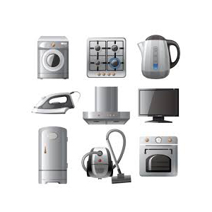
4.1 EMC Compliance Testing in the Electrical and Electronic Field
Electrical and electronic products such as routers and televisions are prone to surge interference in the power grid (such as grid voltage mutations caused by lightning strikes) during use. When using the LISUN SG61000-5 Surge Tester Manufacturers to test a router, parameters are set in accordance with GB/T 17626.5: waveform 1.2/50μs (voltage)/8/20μs (current), voltage 2KV, current 1KA, test times 10 (5 positive, 5 negative), interval time 10s.
Before the test, the router is connected to 220V mains through the built-in coupling/decoupling network to ensure it is in normal working condition (connected to the network and playing videos). During the test, the surge waveform is observed in real-time through the LCD touchscreen to ensure that the waveform parameters meet the standards. After the test, check whether the router has disconnection, crash, abnormal indicator lights, and other issues, and test the signal transmission rate using network speed testing software. When an electronic enterprise tested a new router model, it was found that the router experienced a short disconnection (recovered after about 3 seconds) after applying negative surges. After investigation, it was determined that the varistor in the power module was undersized. After replacing it with a varistor of a higher voltage level, no abnormalities were found in the re-test, and the product successfully passed EMC certification.
4.2 PV Inverter Testing in the New Energy Field
As a core device in new energy power generation systems, PV inverters need to withstand surge interference generated by PV arrays (such as voltage fluctuations caused by cloud discharge). According to IEC 61000-4-5, the LISUN SG61000-5 Surge Tester Manufacturers is used with the following parameters: waveform 1.2/50μs (voltage)/8/20μs (current), voltage 6KV, current 3KA, test times 20 (10 positive, 10 negative), interval time 30s.
Before the test, the DC input terminal of the inverter is connected to the generator through a coupling network, and the AC output terminal is connected to a simulated load (resistor box). The inverter output power is set to 50% of the rated power. During the test, the output voltage, current, and efficiency changes of the inverter are monitored in real-time. After the test, check whether the inverter triggers over-voltage/over-current protection and whether internal components are damaged. When a new energy enterprise tested a PV inverter, it was found that the inverter efficiency dropped by 5% after applying a 6KV positive surge. Analysis showed that the surge resistance of the filter capacitor was insufficient. After replacing it with a high-frequency low-resistance capacitor, the efficiency returned to normal, meeting the grid-connection requirements.
4.3 Base Station Equipment Testing in the Communication Field
The signal lines of base station equipment (such as fiber optic transceiver interfaces) are prone to induced surge interference caused by lightning strikes, affecting signal transmission quality. In accordance with YD/T 1539, the LISUN SG61000-5 Surge Tester Manufacturers is used with the following parameters: waveform 10/700μs (voltage)/5/320μs (current), voltage 4KV, current 2KA, test times 15 (7 positive, 7 negative, 1 alternating), interval time 20s.
Before the test, the base station signal line is connected to the generator through a signal coupling network, and a data transmission link (transmission rate 1000Mbps) is established between the base station and the remote server. During the test, the data packet loss rate and bit error rate are monitored using a network analyzer. After the test, check whether the base station has signal interruption, restart, and other issues. When a communication enterprise tested base station equipment, it was found that the bit error rate increased to 10⁻⁴ (standard requirement ≤10⁻⁶) after applying a 10/700μs waveform surge. By adding a TVS (Transient Voltage Suppressor) diode at the signal line interface, the bit error rate dropped to 10⁻⁷, meeting the communication industry standards.
5. Product Advantages and Usage Precautions of LISUN SG61000-5 Surge Tester Manufacturers
5.1 Product Advantages
• Flexible Adaptation with Modular Design: Voltage and current modules can be freely combined, covering a wide output range of 0~30KV/0~15KA. It meets the diverse testing needs from consumer electronics to industrial equipment, eliminating the need for enterprises to purchase equipment of different specifications repeatedly and reducing testing costs.
• Full Coverage of Multi-standard Waveforms: It supports mainstream standard waveforms such as 1.2/50μs, 10/700μs (for voltage) and 8/20μs, 5/320μs (for current). It can meet the testing requirements of different standard systems including IEC, GB, and YD, adapting to the product certification needs of global markets.
• Built-in Detection Simplifies Operation: It integrates voltage and current attenuator probes as well as an electronic oscilloscope. The LCD touchscreen displays waveforms directly, eliminating the need for external instruments such as oscilloscopes and multimeters. This reduces equipment connection steps, lowers operation complexity, and allows new users to master the basic testing process within 30 minutes.
• High Testing Accuracy and Safety: The waveform parameter error is ≤±10%, and the voltage and current accuracy is ±5%, ensuring reliable test results. At the same time, it is equipped with multiple safety protection functions: it automatically cuts off the power supply in case of overvoltage or overcurrent, and the discharge protection prevents injury from residual charges, safeguarding the safety of operators and equipment.
5.2 Usage Precautions
• Strict Grounding Requirements: The equipment must be connected to an independent grounding electrode, with a grounding resistance ≤4Ω. This avoids surge signal distortion caused by poor grounding and prevents safety accidents due to electrified equipment (enclosure). Before testing, a grounding resistance tester must be used to check the grounding resistance to ensure it meets the requirements.
• Standardized Test Sample Connection: Test samples must be connected through dedicated coupling/decoupling networks. Direct injection of surge signals into test samples is prohibited, as this may damage the samples or affect test results. For example, a power coupling network should be used when testing power lines, and a signal coupling network when testing signal lines; mixing these networks is not allowed.
• Regular Waveform Calibration: It is recommended to calibrate the equipment’s waveform parameters (such as waveform rise time and half-peak time) using a standard waveform calibrator every six months to ensure they meet standard requirements. If abnormal test results occur, the equipment must be calibrated promptly to avoid misjudgment caused by waveform deviations.
• Compliance with Safe Operation Specifications: During testing, operators must wear insulating gloves and insulating shoes, and stand on an insulating mat. Touching the high-voltage output terminal of the equipment and the connection part of the test sample is prohibited. After the test, the equipment’s discharge function must be activated. Only when the residual charge is completely released (the touchscreen shows a voltage of 0) can the test sample connection lines be disassembled.
6. Conclusion
As a professional testing device compliant with international and domestic EMC standards, the Lishan SG61000-5 Lightning Surge Generator provides an efficient and reliable solution for EMC compliance testing in fields such as electronic appliances, new energy, communications, and industrial control through its modular design, multi-standard waveform output, and built-in detection module. Its wide-range voltage and current output capability and user-friendly operation design not only meet the performance optimization testing needs of enterprises in the R&D phase and the factory inspection requirements in the production phase, but also provide authoritative certification testing support for third-party testing institutions.

LISUN’s Motor-Operated Tool | Power Tool Testing solutions strictly comply with a range of core international standards, providing full support for safety and electromagnetic compatibility (EMC)...

LISUN’s electric toy testing solutions cover IEC 62115, EN 71-1, ASTM F963 standards. Including electrical, mechanical, flammability tests to ensure toy safety compliance globally.

LISUN’s transformer test solutions meet IEC 61558-1, IEC 60076-1, IEC 62041 standards. Covering safety, performance, EMC tests, ensuring transformers comply with global requirements.

LISUN’s energy meter testing solutions align with IEC 62052-11, IEC 62053 series standards. Covering safety, electrical, environmental, and EMC tests, we help manufacturers meet global compliance...

LISUN’s household and appliance switch testing solutions meet IEC 60669, IEC 61058, IEC 62271 standards. Covering electrical, mechanical & EMC tests for global compliance.
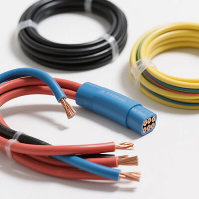
LISUN’s cable and wire test solutions meet IEC 60245-1, IEC 60227-1, IEC 60502-1 and IEC 60189 standards, covering electrical, mechanical, and safety tests for global compliance.
LISUN has all equipment according to the IEC60669 measurement, including environmental chamber, IP code waterproof dustproof test, switch lift test, etc.

Lisun can supply full test solutions for fluorescent lamp, including integrating sphere system, goniophotometer system, EMI EMC test, electronic ballast tester, electrical safety test, etc.

For the CFL design and manufactory, LISUN can supply a full quality control test solution, including photometric, colorimetric, electricity, flicker, IES candela distribution, surge test, electrical...

LISUN’s LED driver test solutions cover lab testing, online testing, EMC/EMI tests, and safety checks, meeting IEC 60335, UL 60335 standards for reliable performance evaluation.

 中文简体
中文简体