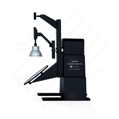
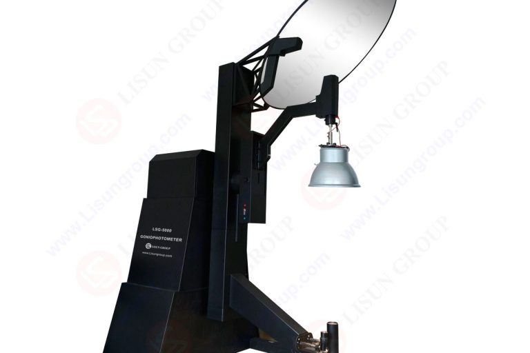
LM-79 Moving Detector Goniophotometer (Mirror Type C)
LSG-6000

High Precision Rotation Luminaire Goniophotometer
LSG-1890B

High Precision Rotation Luminaire Goniospectroradiometer
LSG-1890BCCD

Goniophotometer for Automotive and Signal Lamps
LSG-1950

Goniophotometer for Traffic Signal Lamps
LSG-1950S

Compact Goniophotometer
LSG-1200A

Near Field Moving Detector Goniophotometer
LSG-1900B
Select an organization
to browse standards
Professional lighting evaluation requires correct measurement of luminous distribution and beam shape, light intensity distribution, uniformity and directional output. In current illumination systems, total lumens are no longer a significant consideration and rather accurate angular distribution of light is used to establish compliance, visual comfort, energy efficiency and harmonious beam in practice. A moving detector goniophotometer can supply this requirement as it can record the intensity of light at several angular positions giving scientifically validated photometric results. The knowledge of the goniophotometer working principle also assists the laboratories, manufacturers, and certification agencies to establish proper photometric models.
Directional output is especially required in the real-world applications such as in the architectural spaces, automotive headlights, lighting grids in warehouses and emergency exit luminaires, and roadway optics. Hence, relocated detector systems are the most acceptable luminaire engineering method.
This is the key principle of the moving detector goniophotometer that emitted light on the device under test is mapped geometrical at controlled angles. This detector then rotates along known pre-determined rotational directions, but at a constant distance to the center of measurements. Records of light intensities are made at known angular coordinates which are often given in a C-g or A-B coordinate system.
The instrument will not scale the brightness of random points but each detector reading will give an accurate three-dimensional position. Such readings are then interpolated into complete luminous distribution curves or photometric IES files. Such a method is based on the aspect of the way a luminaire operates in the actual conditions, exposing beam peek, cutoff angle, photometric asymmetry, and luminous spillage.
One of the requirements is to maintain stable geometry. Measurement centers should be maintained in line with optical reference of luminaire. Even the slightest error of 2-3 mm in evaluation of angles will alter candela values and lead to erroneous tests. High-end systems are built with high endurance axis bearings, rotary encoders, and pre-balanced torque systems to maintain mechanical precision.

The light distribution of large luminaires, asymmetric light engines, street fixtures, floodlights or automotive beams is never uniform when they are being evaluated. The measurement of a moving detector goniophotometer can be of hundreds and thousands of angles, according to the requirements of resolution. Increments interpolative error and mathematical accuracy through improvements in the numerical density of measurement points.
Moreover, light distribution is also forced to change with optical lenses, reflectors, secondary diffusers, anti-glare meshes, and refractive covers. Spheres cannot be used to capture these characteristics, as they make average emitted light. Directional response is required on decisions of engineering level.
Contemporary goniophotometers have a scanning path that is rotational. Depending on the type of measurements, the detector can rotate in horizontal, vertical or combinations of two-axis patterns. The intensity values are recorded in real-time with the angle position values during movement. The time constantly is significant because the lamp output can vary due to rising heat particularly during stabilization of LEDs.
After the procuring of raw candela points, the virtualization renders distribution surfaces, polar diagrams, zonal lumen briefs and luminous intensity grids. The datasets are incorporated in the lighting simulation programs by architects and interior designers.
Proper measurement presupposes constant luminous output. LEDs vary dramatically when switched on to electricity. Manufacturers bring the test lamps or modules to full power before the luminous output levels off. Established labs stabilize existing temperatures, junction thermal equilibrium, and thermal uniformity and then rotate the detector.
The increase in temperature does not take place in an equal manner in LEDs. LEDs rely on phosphor conversion which are chromatically shifted when hot. It is a wrong time to measure a premature misrepresentation of rating values.
• Precision on the positioning of detectors during a two-axis motion.
• Fixed distance between detectors and samples.
• Encoded angle resolution
• Atmospheric attenuation correction.
• Cycle repeatability of movement.
• It is the time of thermal stabilization of the luminaire.
• Detector spectral response correction.
Calibration brings the detector output and known luminous intensity standards into constant agreement. Baseline correction is provided by the use of standard lamps whose photometric value could be traced. The glass whose windows are the detector is placed in the center of rotation and the lamp calibrated is in motion between fixed points. In case of differences between the measurement of intensity and the official values, scaling coefficients modify the measurement matrix.
Calibration cycles confirm:
• Detector linearity
• Geometric alignment
• Spectral weighting
• Stray light compensation
Right calibration ensures that it is in line with the IES LM-79 and CIE 121 international testing guidelines.
Goniophotometers also compensate energy drift in long duration scanning since the LED modules can reduce with age.
Light is not propagated straight through, and at edges of secondary reflectors, diffuser, and lateral emission, scattering takes place. In angular scanning, the effects of these scattering regions on the photometric envelope occur. The correctness of the instrument is based on the capability of quantifying secondary dispersion.
In a moving detector goniophotometer high-speed sampling is applied to measure high-speed optical changes. Dissipation Angular regions might be omitted by low-resolution systems leading to false peaks or cutoff angles.
Engineers Export IES or LDT files which represent intensity distribution when precision optical analysis is done. Such files are loaded into illumination programs to calculate uniformity maps, roadway spacing, indoor reflectance behavior and glare values.
Table: Typical angular scanning resolution ranges used in goniophotometry
| Measurement Type | Angular Step Size | Typical Candela Data Count |
| Basic directional evaluation | 5° | 72 to 144 data points |
| Professional luminaire testing | 2.5° | 144 to 288 data points |
| Automotive or asymmetric fixtures | 1° | 720+ data points |
| High-precision beam profiling | 0.5° | 1400+ data points |
Measurement is affected by system inertia, bearing quality and structural rigidity. The smallest micro-movement or vibration is detected and changes the detector alignment and reading value. This is of critical concern when using long fixtures in which the optical emission center is too distant to the mounting brackets.
Instruments of professional grade are used:
• Reinforced steel arms
• Micro-bearing axis rotation
• Counterbalanced lamps mounts.
• Accurately encoded movement gears
These also provide stability of measurement geometry even when doing large rotations sweeps.
Photometers do not work to give lighting diagrams, but to give luminous intensity numbers. Raw output is converted into software processing to produce:
• Candela-vs-angle curves
• Multi-plane polar profiles
• Multi- quadrant bright visualizations.
• Zonal lumen tables
• Asymmetric beam layouts
• Light distribution files
Majority of the laboratories export the measurement set into IES based tools, roadway lighting design programmes, tunnel lighting evaluation systems and architectural simulation to submit compliance. The LISUN supplies instrument platforms that incorporate the interface of analytical engines so that visualization can be done directly with no external programming.
Making a precision photometric analysis needs not only the values of luminous flux; angularly resolved behavior is needed. This capability is offered by a moving detector goniophotometer which measures directional intensity by rotating within controlled direction. Geometric consistency and detector calibration, thermal stabilization and controlled scanning resolution result in accuracy.
With a good knowledge of the principle of the goniophotometer working, the laboratories produce steady datasets that facilitate the engineering decision in real world. Under correctly designed measuring cycles and fine instrumentalization, such as the LISUN complexes, manufacturers now have directional photometric data of actual share of fixtures performance instead of ratified optical production.
Lisun Instruments Limited was found by LISUN GROUP in 2003. LISUN quality system has been strictly certified by ISO9001:2015. As a CIE Membership, LISUN products are designed based on CIE, IEC and other international or national standards. All products passed CE certificate and authenticated by the third party lab.
Our main products are Goniophotometer, Integrating Sphere, Spectroradiometer, Surge Generator, ESD Simulator Guns, EMI Receiver, EMC Test Equipment, Electrical Safety Tester, Environmental Chamber, Temperature Chamber, Climate Chamber, Thermal Chamber, Salt Spray Test, Dust Test Chamber, Waterproof Test, RoHS Test (EDXRF), Glow Wire Test and Needle Flame Test.
Please feel free to contact us if you need any support.
Tech Dep: Service@Lisungroup.com, Cell/WhatsApp:+8615317907381
Sales Dep: Sales@Lisungroup.com, Cell/WhatsApp:+8618117273997
LISUN’s indoor and outdoor LED test solutions meet IEC 60598-1, IEC 62722-2-1, CIE 121 standards, covering safety, photometry, and environmental tests for global compliance.

 中文简体
中文简体