LM-79 Moving Detector Goniophotometer (Mirror Type C)
LSG-6000

High Precision Rotation Luminaire Goniophotometer
LSG-1890B

High Precision Rotation Luminaire Goniospectroradiometer
LSG-1890BCCD

Goniophotometer for Automotive and Signal Lamps
LSG-1950

Goniophotometer for Traffic Signal Lamps
LSG-1950S

Compact Goniophotometer
LSG-1200A

Near Field Moving Detector Goniophotometer
LSG-1900B
Select an organization
to browse standards
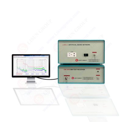
A crucial piece of equipment for EMC testing is a spectrum analyzer. Spectrum analyzers with EMC-specific capabilities have become much more affordable in recent years. Spectrum analyzers offer a wide variety of parameter settings and must be set up properly. This is done in order to produce measurements as close as possible to the specifications of the particular EMC standards that apply to the product’s design and end-use.
The proper instrument parameters for the RBW filter, video bandwidth, detector type, frequency span, and sweep duration are determined by EMC standard-related criteria. The necessary parameters are also influenced by transducer properties and radiation restrictions. Thus, the instrument must be optimized to achieve a suitable balance between high sensitivity and minimal distortion.
Spectrum Analyzers
Tests used to assess frequencies and numerous other factors are done through spectrum analyzer. It is interesting that spectrum analyzers are used to measure known signals and discover unknown signals. Spectrum analyzer has many uses in the realm of electrical and electronic measurements because of its accuracy. Numerous circuits and systems are tested using it.
These systems and circuits function at radio frequency levels. A spectrum analyzer initially has a similar appearance to an oscilloscope. Many modern, powerful oscilloscopes come equipped with built-in spectrum analyzers. An oscilloscope primarily accesses signals using probes or cables attached to analog inputs. Two axes are used to display these signals. The amplitude is shown on the Y-axis in volts. While the time is shown on the X-axis.

Beat frequency is the result of combining two frequencies. It will be noted that when two acoustic tones are present simultaneously and are sufficiently near in frequency, a third tone will also be audible. The frequency of the resulting tone will decrease as one of the two original tones is moved closer to the other. It takes on a distinctive beating sound until it abruptly vanishes when the two original tones exactly coincide. This phenomenon results from the alternation of constructive and destructive interference, which shapes the final tone.
Every frequency that the tuner chooses must be produced by the oscillator at a separate frequency in order for the IF to remain stable. The initial method was for each radio station to broadcast the waveform necessary to enable the superheterodyne operation together with the RF signal. The range of tones being created within each receiver was soon proven to be more effective. You may have seen a two-gang variable capacitor with two sets of plates of various sizes attached to a single shaft inside an old tube-type radio.
This configuration offered the proper capacitances. It enabled the creation of a single stable IF by synthesizing the right frequency to work against each broadcast carrier. This may be boosted without RF processing. This results in a significant amount of attenuation. LISUN produced EMI receivers and spectrum analyzers are best in the market and can be used to test out your product. Now we will get into the working principle of this device and see how you can efficiently use it.
Spectrum Analyzer Working Principle
The spectrum analyzer quantifies the signal’s spectrum content as it is delivered into the device. The device would measure the spectrum content of the output filter in the frequency domain if we were monitoring the output of a filter, let’s say a low pass filter. Additionally, the noise content would be measured during this operation and displayed in the CRO.
The input attenuator attenuates the radio frequency level signal before feeding it to the measured signal. This is to create the horizontal sweep of the measured signal. The low pass filter receives the output of the attenuator to remove any ripple content from the signal. After that, it is fed into an amplifier. This increases the signal’s strength to a specific level.

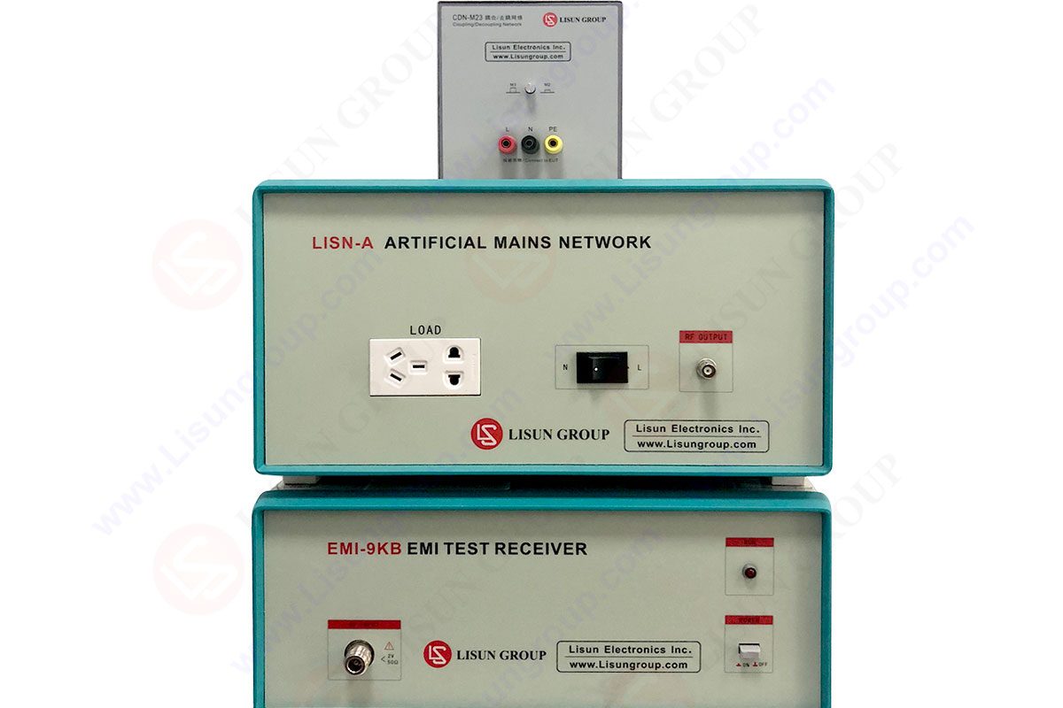
EMI-9KB EMI Test Receiver
It is combined with the oscillator’s output. This is adjusted to a specific frequency throughout this procedure. The oscillator contributes to the fed waveform’s alternating character. The signal is supplied to the horizontal detector. It transforms it into the frequency domain after being combined with the oscillator and amplified.
The spectral quantity of the signal is displayed in the frequency domain right here in the spectrum analyzer. It is necessary to have the amplitude for the vertical sweep. The signal is supplied to the voltage tuned oscillator to obtain the amplitude. Radio frequency tuning is used with the voltage tuned oscillator. Typically, oscillator circuits are created using a combination of resistors and capacitors. These are called RC oscillators. The signal undergoes a 360-degree phase shift at the oscillator level. Different levels of RC circuits are employed for this phase shifting. We typically have three layers.
The usage of transformers for phase-shifting occurs occasionally as well. A ramp generator is also used to adjust the oscillators’ frequency most of the time. The ramp generator may also be coupled to a pulse width modulator to create a ramp of pulses. The vertical sweep circuit receives the oscillator’s output. This gives the cathode ray oscilloscope amplitude. Spectrum analyzers are of two types which are discussed below.
Analog Spectrum Analyzer
The superheterodyne principle is used in analog spectrum analyzers. They are additionally known as sweep or swept analyzers. The analyzer will contain several horizontal and vertical sweep circuit. A logarithmic amplifier is also used before to the horizontal sweep circuit. This is used to display the output in decibels. A video filter is also offered to filter the video material. Each frequency can display the frequency response in a different area on the display thanks to the ramp generator.
Digital Spectrum Analyzer
Fast Fourier transform (FFT) and analog to digital converters (ADC) blocks are used in the digital spectrum analyzer. These are used to turn analog signals into digital signals. The attenuator lowers the signal’s level before feeding the signal to the LPF. This removes the ripple content. An analog to digital converter (ADC) is then used to transform the signal to the digital realm. The FFT analyzer receives the digital signal and translates it into the frequency domain. Measuring the signal’s frequency spectrum is useful. Finally, the CRO is used to display it.
Lisun Instruments Limited was found by LISUN GROUP in 2003. LISUN quality system has been strictly certified by ISO9001:2015. As a CIE Membership, LISUN products are designed based on CIE, IEC and other international or national standards. All products passed CE certificate and authenticated by the third party lab.
Our main products are Goniophotometer, Integrating Sphere, Spectroradiometer, Surge Generator, ESD Simulator Guns, EMI Receiver, EMC Test Equipment, Electrical Safety Tester, Environmental Chamber, Temperature Chamber, Climate Chamber, Thermal Chamber, Salt Spray Test, Dust Test Chamber, Waterproof Test, RoHS Test (EDXRF), Glow Wire Test and Needle Flame Test.
Please feel free to contact us if you need any support.
Tech Dep: Service@Lisungroup.com, Cell/WhatsApp:+8615317907381
Sales Dep: Sales@Lisungroup.com, Cell/WhatsApp:+8618117273997

LISUN’s Motor-Operated Tool | Power Tool Testing solutions strictly comply with a range of core international standards, providing full support for safety and electromagnetic compatibility (EMC)...

LISUN’s transformer test solutions meet IEC 61558-1, IEC 60076-1, IEC 62041 standards. Covering safety, performance, EMC tests, ensuring transformers comply with global requirements.

LISUN’s household and appliance switch testing solutions meet IEC 60669, IEC 61058, IEC 62271 standards. Covering electrical, mechanical & EMC tests for global compliance.

LISUN provide full test solutions for HID lamp, including integrating sphere system, goniophotometer system, EMI EMC chamber, HID ballast tester, electrical safety test, etc.

Lisun can supply full test solutions for fluorescent lamp, including integrating sphere system, goniophotometer system, EMI EMC test, electronic ballast tester, electrical safety test, etc.

For the CFL design and manufactory, LISUN can supply a full quality control test solution, including photometric, colorimetric, electricity, flicker, IES candela distribution, surge test, electrical...

 中文简体
中文简体