
LM-79 Moving Detector Goniophotometer (Mirror Type C)
LSG-6000

High Precision Rotation Luminaire Goniophotometer
LSG-1890B

High Precision Rotation Luminaire Goniospectroradiometer
LSG-1890BCCD

Goniophotometer for Automotive and Signal Lamps
LSG-1950

Goniophotometer for Traffic Signal Lamps
LSG-1950S

Compact Goniophotometer
LSG-1200A

Near Field Moving Detector Goniophotometer
LSG-1900B
Select an organization
to browse standards
I.Basic knowledge of EMI receiver
EMI receiver, also known as Electromagnetic Interference Measurement Instrument, is the most widely used and basic measuring instrument in electromagnetic compatibility test. It is essentially a tuned measuring instrument which can selectively identify the pre-set frequency components from the interference signals received from the sensors, and display and record them in fixed frequency band. It can be regarded as a adjustable, frequency-directional, precisely measuring voltmeter.
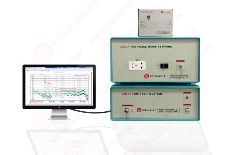
LISUN EMI receiver system for EMI (Electromagnetic Interference) radiation conduction or conducted emissions testing. The EMI-9KB EMI receiver is made of full closure structure and strong electro-conductibility material, which has high shielding effect. Due to the new technology for the EMI Test System, it solved the instrument self-EMI problem. The test results are according to the international format test report. The EMI Test System EMI-9KB fully meets CISPR15:2018, CISPR16-1, GB17743, FCC, EN55015 and EN55022.

EMI-9KB EMI Test Receiver
II.The working principle of EMI receivers
When measuring the signal by EMI receiver, the instrument is tuned to a measurement frequency fi. After passing through a high-frequency attenuator and a high-frequency amplifier, the frequency is mixed with the local oscillator frequency f1 to produce many mixed signals. After passing through the intermediate frequency filter, only intermediate frequency fo = f1-fi is obtained. The intermediate frequency signal is amplified by the intermediate frequency attenuator and intermediate frequency amplifier, and then detected by the envelope detector. After low frequency amplification, it can drive the meter indication or display on the digital tube screen.
The EMI receiver measures the voltage of the signal input to its port. To measure field strength or interference current, a transformer is used to transform the port voltage measured into field strength (unit uV/m or dBV/m), current (unit A, dBA) or power (unit W, dBmW) according to the transformation coefficient. The transformer may be an antenna, a current probe, a power absorber clamp, or a power impedance stabilizing network depending on the object to be measured.
III.Method of scanning an EMI Receiver
1. Average Value Detection: Its greatest feature is that the charging and discharging time constant of the detector is the same, especially suitable for continuous wave measurement. The Integral time constant can reach the second level.
2. Peak Detection: Its charging time constant is very small (100ns), even very narrow pulse can be quickly charged to a steady value. When the intermediate frequency signal disappears, due to the long discharge time constant (up to 100s) of the circuit, the output voltage of the detector can remain at the peak value for a long period of time. Peak detection is first used in military interference emission experiments because many military devices only require a single pulse stimulation to cause explosions or digital device misoperations, without the need for audio devices to pay attention to time accumulation.
3. Quasi-peak Detection: The charging time constant of this detector is between the average value and the peak value (the charging time constant is about 1ms and the discharging time constant is about 160ms). In the measurement cycle, the detector output is related to the pulse amplitude and repetition frequency, and its output is consistent with the effect of interference on the auditory sense. Because the interference in the early CISPR research was the interference in the broadcast system, the quasi-peak detector was recommended in the CISPR publications, which was very suitable for describing the characteristics of radio interference noise.
4. Effective Value Detection: Random noise refers to the noise emitted by some electronic components during operation, and noise caused by crosstalk and other noise in the process of information transmission. Its characteristics are chaotic, and some random noises (such as thermal noise and particulate noise) obey the normal distribution rule. For them, the peak value is worthless. Therefore, effective value and average value detection are generally used. In EMI testing, effective value detection is used the least.
IV.Comparison between EMI Receiver and Spectrum Analyzer
Through the introduction of EMI receivers, we know that they have similarities with spectrum analyzers, which use superheterodyne structures and display the amplitude of each frequency component. But they also have differences, mainly reflected in the following aspects:
1. The signal processing performed at the input end of the receiver and spectrum analyzer is different. The signal input end of the spectrum analyzer usually has a set of simple low-pass filters, while the receiver needs to use a preselector with strong anti-interference ability for wideband signals, usually including a set of fixed bandpass filters and a set of tracking filters to complete the preselection of the signal.
2. The scanning signal is different. The scanning signal source of the spectrum analyzer is usually controlled by a sawtooth or stepping signal to achieve the desired mixing output signal, and the frequency changes are continuous.
The frequency scanning of the receiver is discrete point frequency measurement. The receiver measures the level according to the preset frequency interval. It is controlled by the processor to measure the level at each frequency point, and the test result curve displayed is actually the result of single point frequency test. Now in EMI test, people not only require manual tuning to search for frequency points, but also require fast and intuitive observation of the frequency level characteristics of the EUT. This is what the beat signal cannot achieve.
3. The bandwidth definition of intermediate frequency filters is different.
Generally, the resolution bandwidth of the spectrum analyzer is the 3dB bandwidth of the amplitude frequency characteristic, while the intermediate frequency bandwidth of the receiver is the 6dB bandwidth of the amplitude frequency characteristic.
4. The detectors are different.
The spectrum analyzer usually has peak and average detectors. In addition to this, the receiver also has quasi-peak detectors and root-mean-square detectors.
5. The test accuracy is different.
From the signal processing of the receiver and the requirements of EMC test, the receiver should have higher accuracy and lower spurious response than the spectrum analyzer.Based on the above comparison analysis, we can summarize a simple formula:
General spectrum analyzer + preselector + 6dB intermediate frequency filter + three kinds of detectors + point frequency test function + high precision signal processing = EMI receiver
This formula dramatically explains the similarities and differences between the spectrum analyzer and EMI receiver. However, it should be noted that the items on the left side of the formula are not simply listed, each of which has special requirements. That is to say, if the receivers modified from the spectrum analyzers are used for testing, they must meet the corresponding standards. Those that do not meet the standards can only be used as predictive equipment. On the current market, we can see some that have been modified from the spectrum analyzers.
Instrument such as spectrum analyzer built-in 6dB intermediate frequency bandwidth, peak and average value waveform, or spectrum analyzer plus pre-selector, etc., can not meet the requirements of the receiver completely. It can only be used for factory pre-test. The receiver designed for EMC test is the only choice for judgment and certification test.
V.Basic operations of EMI receiver

1. To set the test frequency range: Press the sweep key, then press USE Scan Table, the following interface will appear to set.
2. To set Peak/QP/AV measurement: First press Meas, then press detector key, so you can select Peak/QP/AV. To set Max Hold, press DISP.
3. After completing the parameter settings, press sweep and press run scan to test.
Lisun Instruments Limited was found by LISUN GROUP in 2003. LISUN quality system has been strictly certified by ISO9001:2015. As a CIE Membership, LISUN products are designed based on CIE, IEC and other international or national standards. All products passed CE certificate and authenticated by the third party lab.
Our main products are Goniophotometer, Integrating Sphere, Spectroradiometer, Surge Generator, ESD Simulator Guns, EMI Receiver, EMC Test Equipment, Electrical Safety Tester, Environmental Chamber, Temperature Chamber, Climate Chamber, Thermal Chamber, Salt Spray Test, Dust Test Chamber, Waterproof Test, RoHS Test (EDXRF), Glow Wire Test and Needle Flame Test.
Please feel free to contact us if you need any support.
Tech Dep: Service@Lisungroup.com, Cell/WhatsApp:+8615317907381
Sales Dep: Sales@Lisungroup.com, Cell/WhatsApp:+8618117273997

LISUN’s Motor-Operated Tool | Power Tool Testing solutions strictly comply with a range of core international standards, providing full support for safety and electromagnetic compatibility (EMC)...

LISUN’s transformer test solutions meet IEC 61558-1, IEC 60076-1, IEC 62041 standards. Covering safety, performance, EMC tests, ensuring transformers comply with global requirements.

LISUN’s household and appliance switch testing solutions meet IEC 60669, IEC 61058, IEC 62271 standards. Covering electrical, mechanical & EMC tests for global compliance.

For the CFL design and manufactory, LISUN can supply a full quality control test solution, including photometric, colorimetric, electricity, flicker, IES candela distribution, surge test, electrical...

 中文简体
中文简体