
LM-79 Moving Detector Goniophotometer (Mirror Type C)
LSG-6000

High Precision Rotation Luminaire Goniophotometer
LSG-1890B

High Precision Rotation Luminaire Goniospectroradiometer
LSG-1890BCCD

Goniophotometer for Automotive and Signal Lamps
LSG-1950

Goniophotometer for Traffic Signal Lamps
LSG-1950S

Compact Goniophotometer
LSG-1200A

Near Field Moving Detector Goniophotometer
LSG-1900B
Select an organization
to browse standards
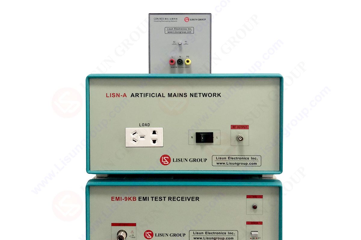
EMI receivers are defined as the high performance instrumentation that acquire data for analysis. EMI receivers are used in the scenarios where transient signals or spurious emissions appear and are acquired with fast acquisition rates.

EMI Test Receiver
EMC stands for ‘’electromagnetic compatibility’’. We conduct this test to ensure that our product does not interfere with another product within the electromagnetic medium. On the other hand, we don’t want emissions from the other devices to interrupt the operation of our device. EMC testing is done via the EMC testing equipment.
Apart from these two conditions, we want to ensure that our device does not stop malfunctioning because of somebody else’s device.
The test falls into two major categories; emissions and immunity. Emission is primarily concerned with what your product is emitting and what kind of RF frequencies your product is emitting. Immunity is concerned with how immune your product is from other emitters of RF energy emissions.

These tests have been divided into two main categories; Conducted emission test and Radiated emission test.
Radiated emissions testing is defined as the measurement of the electromagnetic field of the emissions that are unintentionally generated by the equipment under test. In order to cover the entire frequency range of interest, several different antennas may be required.
Radiated emission test is concerned about how much your product is emitting in terms of RF energy, and we have to make these measurements in order to make sure that we comply with the law. Suppose we are trying to measure the number of emissions that we have got from our device under test that is our product. What we don’t want to happen is emission from other devices such as mobile phones, radio masts, or TV signals to corrupt a measure.
Therefore, we have to do this measurement somewhere that is sealed like a Faraday Cage, and that is our test chamber. It is a metal box, a big metal box where we test our equipment. This metal box stops the external signals from getting in.
The other problem is if the metal box reflects all of these RF signals. Our equipment inside the metal box is going to emit, and it will reflect off the walls. It’s going to get picked up by an antenna. So, this test is done in an anechoic or semi-anechoic chamber.
The test setup is defined in the standard, and it may vary slightly depending on the product and its application. Typically, it is a wooden table and an antenna. The device under test is placed on the wooden table, and an antenna picks the emissions from this table. After this, it is compared against a limit line which is again defined in the slab.
The device under test is usually placed on a wooden table. In order to make sure that the antenna will pick up all the emissions from your device, the table is usually rotated. So, the antenna can pick up the entire 360 degrees of emissions. The orientation of the antenna would give the maximum emission stitches picked up, which has to be under the limit line of the standard.
The device, in this case, is a bully 100 vector network analyzer. This is a USB control device. So, we connect this to a laptop or a PC. We can not put the laptop here on the table because it would be dangerous. Provisions are made for the USB cable to go down the table through some decoupling clamps.
Put through this hatch to the outside of the chamber. So, we can close it. Now, we are ready to perform the test.
• Close the test chamber. The test chamber is stopping all RF emissions from getting in. The fact that we wear a radio mic and as soon as we shut the door. We will lose the signal from the mic and hear a static sound.
• The cable from the antenna comes through the test chamber and is connected to the receiver.
• The receiver will measure the emissions from the device on the test.
• It will display it on the laptop. Now, you will see a red limit line, and you can see that, at least for this one particular test, we are well below that limit line.
• We need to turn the table and look at all the angles as the table rotates.
• In addition to the rotation of the table, we should also change the antenna’s orientation and the combination of different rotation angles and different orientations on the antenna.
We have completed our pre-compliance test, and therefore, we have a lot of confidence that we can pass the full EMC test in a test chamber.
The standards required in the conducted emission test to make sure that the amount of RF energy on the cables of any device is not above a certain limit. It is going to cause a disturbance with other devices effectively. Any cable that comes out of the device needs to be tested from all the ports, much like the radiated emissions. In that case, you did not want your device on the test to emit the radio frequency emissions in the air.
We have bully 100, which is again the device under test, and we are trying to measure the conducted emissions of the cables in this particular case. We are also measuring the power port. The power cable and the power supply get connected to the test device called a V Network. The job of this unit is to make sure that the power port we are trying to measure seems to be a stable impedance.
This unit is trying to stop the emissions on the power lines that are powering the whole test instrument from corrupting the measurement. On this network, there is a port defined as a standard, and the output of this is the RF noise that we are going to measure. The receiver will measure the emissions on the frequency band of interest. It will give a limit line again.
If you are above the limit line, you have failed the test. Typically, in the case of power supply, you would look at designing, perhaps a better filter. On the other hand, you have beautifully passed the test if you are below the line. We need to measure the line and neutral both effectively. We press the second button, and it measures the neutral.
Thus, there are many other tests within the group of conducted emissions. In addition, the RF conducted emission test depends on the product and application of the power rating.
One of the most important applications of conducted emission tests is the Line Current Harmonics requirement of the standard. In this process, we are talking about the low-frequency line harmonics. The product injects onto the power lines instead of the RF frequency range.
It is the power factor correction requirement. The standard says that the current that the product is drawing from the mains has to be as close to a sinusoid as possible. You can also take a very peaky current to deliver the same amount of power. But, of course, if you choose, the peak of the current you are drawing is very large. It has an impact on the cabling and the shielding.
Thus, this standard prohibits you from being able to have too many line current harmonics, but that is much lower frequencies. It is effectively around the multiples of the line frequency imaging.
Lisun Instruments Limited was found by LISUN GROUP in 2003. LISUN quality system has been strictly certified by ISO9001:2015. As a CIE Membership, LISUN products are designed based on CIE, IEC and other international or national standards. All products passed CE certificate and authenticated by the third party lab.
Our main products are Goniophotometer, Integrating Sphere, Spectroradiometer, Surge Generator, ESD Simulator Guns, EMI Receiver, EMC Test Equipment, Electrical Safety Tester, Environmental Chamber, Temperature Chamber, Climate Chamber, Thermal Chamber, Salt Spray Test, Dust Test Chamber, Waterproof Test, RoHS Test (EDXRF), Glow Wire Test and Needle Flame Test.
Please feel free to contact us if you need any support.
Tech Dep: Service@Lisungroup.com, Cell/WhatsApp:+8615317907381
Sales Dep: Sales@Lisungroup.com, Cell/WhatsApp:+8618117273997

LISUN’s Motor-Operated Tool | Power Tool Testing solutions strictly comply with a range of core international standards, providing full support for safety and electromagnetic compatibility (EMC)...

LISUN’s transformer test solutions meet IEC 61558-1, IEC 60076-1, IEC 62041 standards. Covering safety, performance, EMC tests, ensuring transformers comply with global requirements.

LISUN’s household and appliance switch testing solutions meet IEC 60669, IEC 61058, IEC 62271 standards. Covering electrical, mechanical & EMC tests for global compliance.

For the CFL design and manufactory, LISUN can supply a full quality control test solution, including photometric, colorimetric, electricity, flicker, IES candela distribution, surge test, electrical...

 中文简体
中文简体