As the speed of integrated circuits is getting faster and the density is getting bigger and bigger, there will inevitably be interference problems, and we must solve this interference.
Why should integrated circuits pass EMI/EMC testing? Strictly speaking, all electronic devices require EMI/EMC testing. Electronic devices with excessive EMI/EMC not only work unstable, but also affect other electronic devices, such as radiated EMI/EMC and even radiated EMI/EMC. affect the human body.
With the advancement of science and technology, smart home has gradually entered the family life of ordinary residents, which is bound to be the development trend of future lifestyles. In the current smart home equipment market, it can be described as rich and colorful. The networking methods of various devices are different, and they also have their own advantages in terms of cost, power consumption, distance and other characteristics. Of course, the different networking methods also directly affect the control technology. At present, the well-known networking methods include wifi, Zigbee and Bluetooth, etc. In the second half, we will also take a look at some of the current wireless transmission rules.

EMI/EMC in dalily life
What is EMI/EMC
EMC Introduction:
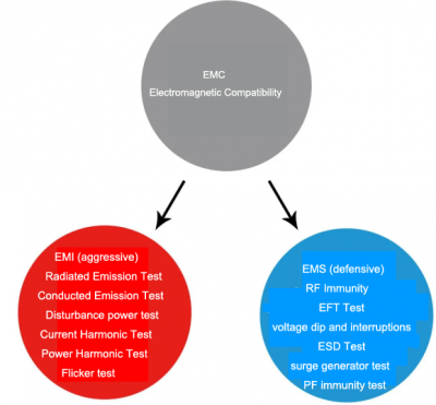
EMC (Electro Magnetic Compatibility) literally translates to “electromagnetic compatibility”. The term EMC has a very broad meaning. It means that the electromagnetic energy generated by the equipment neither interferes with other equipment nor interferes with the electromagnetic energy of other equipment. Just like a blind man touching an elephant, there is a big difference between what you touch and what actually is. In particular, electromagnetic phenomena that are contrary to the design intent are regarded as EMC problems. Electromagnetic energy detection, anti-electromagnetic interference test, statistical processing of detection results, electromagnetic energy radiation suppression technology, natural electromagnetic phenomena such as lightning and geomagnetism, the influence of electric and magnetic fields on the human body, international standards of electric field strength, transmission methods of electromagnetic energy, Relevant standards and restrictions are included in EMC.
EMI Introduction:
EMI (Electromagnetic Interference) “Electromagnetic Interference” can be understood as attack type. There are two types of EMI, conducted interference and radiated interference. Conducted interference refers to the coupling (interference) of a signal on one electrical network to another electrical network through a conductive medium. Radiated interference refers to the interference source coupling (interfering) its signal to another electrical network through space. In high-speed PCB and system design, high-frequency signal lines, integrated circuit pins, various connectors, etc. may become radiation interference sources with antenna characteristics, which can emit electromagnetic waves and affect other systems or other subsystems normal work. The so-called “interference” refers to the two-layer meaning of the interference source that the performance of the device is degraded and the interference to other devices is caused. The first level of meaning is such as thunder and lightning making radio noises, snowflakes appearing on the TV screen after a motorcycle is driving nearby, and radio sounds after picking up the phone. These can be referred to as “BCI (radio)” and “TVI (TV)” for short “TelI (radio)”, these abbreviations all have the same “I” (interference), so what part of EMI are EMI standards and EMI detection? Of course, it is the second layer of meaning, that is, the source of interference, which also includes the electromagnetic energy before the interference.
EMS introduction:
EMS (Electro Magnetic Susceptibility) literally translates to “electromagnetic sensitivity”, which we can understand as defensive type, which means the ease of performance degradation due to electromagnetic energy. For the sake of easy understanding, we compare electronic equipment to people, and compare electromagnetic energy to cold viruses. Sensitivity is whether it is easy to catch a cold. If it is not easy to catch a cold, it means that the immunity is strong, that is, the English word Immunity, that is, strong anti-electromagnetic interference.

Introduction for EMI/EMC/EMS
Measurement indicators of Bluetooth and WI-FI
Output Power:
The initial state of the trace tester is set as follows: the link is frequency hopping, and the EUT is set to loopback. The tester transmits the payload of PN9, and the packet type is the packet of the maximum length supported. The EUT decodes the packet sent by the tester, and uses the same packet type to send the payload back to the tester with its maximum output power. The tester measures peak and average power over the entire burst range at low, mid and high frequencies. The specification requires that the peak power and average power are less than 23dBm and 20dBm respectively, and meet the following requirements: if the power level of the EUT is 1, the average power is > 0dBm; if the power level of the EUT is 2, -6dBm<average power<4dBm; The power level is 3, and the average power is <0dBm.
Power Density:
The initial state is the same (output power), the tester finds the frequency point corresponding to the maximum power within the 240MHz frequency band by sweeping the frequency, and then performs time domain scanning (scanning time is 1 minute) at this frequency point, and measures the maximum value. Less than 20dBm/100kHz.
Power Control:
The initial state is loopback, not frequency hopping. The EUT works at three frequency points of low, medium and high respectively, and sends back the DH1 packet whose modulated signal is PN9. The tester controls the EUT output power through LMP signaling, and tests the range of the power control step size, which is required by the specification to be between 2dB and 8dB.
Frequency Range:
The initial state is the same (power density), and the tester measures the frequency sweep of the DH1 packet whose payload is PN9 sent back by the EUT. When the EUT works at the lowest frequency point, the tester finds the frequency point fL when the power density drops -80dBm/Hz; when the EUT works at the highest frequency point, the tester finds the frequency point when the power density drops to -80dBm/Hz fH. For a 79-channel system, fL and fH are required to be in the range of 2.4 to 2.4835 GHz.
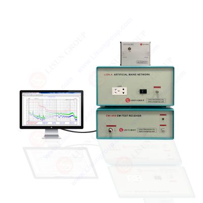
LISUN design EMI Test System EMI-9KB fully meets CISPR15:2018, CISPR16-1, GB17743, FCC, EN55015 and EN55022. Detection frequency range: 9kHz~1GHz (EMI-9KC), 9kHz~300MHz (EMI-9KB), 9kHz~30MHz (EMI-9KA) .

EMI-9KB EMI Receiver System

9K-30MHz Test Report

30M-300MHz Test Report
Lisun Instruments Limited was found by LISUN GROUP in 2003. LISUN quality system has been strictly certified by ISO9001:2015. As a CIE Membership, LISUN products are designed based on CIE, IEC and other international or national standards. All products passed CE certificate and authenticated by the third party lab.
Our main products are Goniophotometer, Integrating Sphere, Spectroradiometer, Surge Generator, ESD Simulator, EMI Receiver, EMC Test Equipment, Electrical Safety Tester, Environmental Chamber, Temperature Chamber, Climate Chamber, Thermal Chamber, Salt Spray Test, Dust Test Chamber, Waterproof Test, RoHS Test (EDXRF), Glow Wire Test and Needle Flame Test.
Please feel free to contact us if you need any support.
Tech Dep: Service@Lisungroup.com, Cell/WhatsApp:+8615317907381
Sales Dep: Sales@Lisungroup.com, Cell/WhatsApp:+8618917996096
Your email address will not be published. Required fields are marked *