LM-79 Moving Detector Goniophotometer (Mirror Type C)
LSG-6000

High Precision Rotation Luminaire Goniophotometer
LSG-1890B

High Precision Rotation Luminaire Goniospectroradiometer
LSG-1890BCCD

Goniophotometer for Automotive and Signal Lamps
LSG-1950

Goniophotometer for Traffic Signal Lamps
LSG-1950S

Compact Goniophotometer
LSG-1200A

Near Field Moving Detector Goniophotometer
LSG-1900B
Select an organization
to browse standards
There is no doubt that safety is a paramount concern in any industry. That’s why at LISUN, we focus on ensuring the highest level of safety in our glow wire testing products.
1. Glow wire tester application:
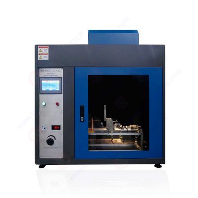
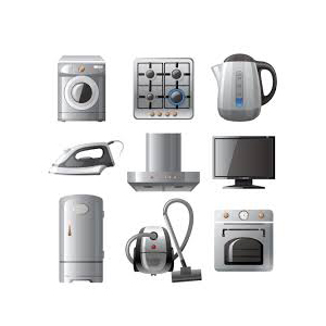
The glow-wire tester uses simulation technology to evaluate the fire hazard caused by heat sources such as glowing components or overload resistors in a short time due to thermal stress. It is one of the series of electrical and electronic components fire hazard test instruments. It is suitable for evaluating the flammability test and ignition temperature test of electrical equipment and its components and parts, as well as solid electrical insulating materials or other solid flammable materials. LISUN designed and manufacture ZRS-3H glow wire tester is mainly used to test the ignition performance, ignition temperature, flammability and flammability index of lighting equipment, electronic products and household appliances. The equipment adopts high-temperature sprayed steel structure and imported instrument display, which is easy to operate and has stable test performance. This set of equipment is mainly used for flame retardancy testing of quality supervision departments and related enterprises.

Standard:
The ZRS-3H Glow-wire Test Apparatus is according to IEC60695-2-1, IEC60695-2-10, IEC60695-2-11, IEC60695-2-12, IEC60695-2-13 (GB/T5169.10, GBT5169.11, GBT5169.12, GB/T5169.13) < basic testing methods of Glow wire, basic testing methods of Glow wire device>, UL 746A, IEC829, DIN695 and VDE0471.

ZRS-3H Glow-wire Test Apparatus
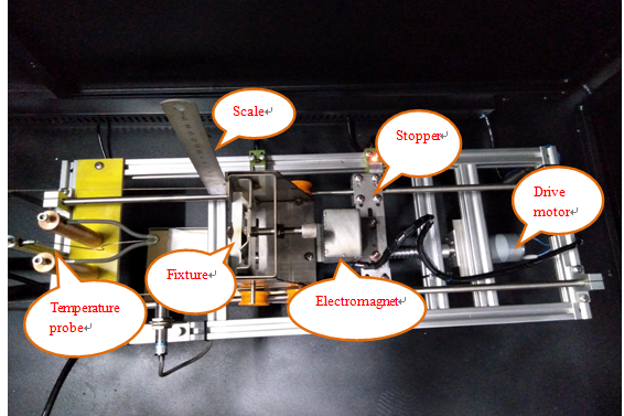
2. Internal Mechanical Structure

Internal Mechanical Structure

Internal Mechanical Structure
3. Test principle:
I. Use simulation technology to evaluate the fire hazard caused by thermal stress caused by heat sources such as hot components or overload resistors in a short period of time.
II. The glow wire is a specified resistance wire loop, which is heated to a specified temperature by electricity. The tip of the glow wire contacts the sample for a specified period of time, and the properties of the material are observed and measured.
III. This test device is used for ignition test without flame ignition source.
4. Maintenance
4.1 Glow wire inspection
Before each batch of tests, the top dimension “A” after bending of the glow wire must be measured and recorded. The size should be compared with subsequent tests, and the glow wire should be replaced when the size is reduced to 90% of the initial reading;
After each test, the top of the glow-wire must be removed, if necessary, from all residues of the previously tested material, for example with a wire brush, and the top of the glow-wire must be inspected for cracks.
4.2 Replacing the Glow Wire and Thermocouple
If the glow wire and thermocouple are damaged or one of them is damaged, please replace a complete set of 1.0mm or 0.5mm glow wire and matching thermocouple in time.
Replacement operation: first turn off the power; loosen the glow wire fastening screw and remove the glow wire; loosen the thermocouple fastening screw, open the side case, and remove the thermocouple electrode; install the glow wire and tighten it to ensure that the glow wire extension length is 70mm; the thermocouple is installed and fastened, and the thermocouple is placed in the small hole of the glow wire; the thermocouple wire is passed into the side case, and the thermocouple electrodes are installed at the No. 9 and No. 10 electrodes of the temperature control meter.
4.3 Calibration of the temperature system
When a new thermocouple or glow wire is exchanged and the accumulated usage time is large, the temperature system (the drift of the thermocouple) needs to be calibrated. A random password is required for calibration, the default password is “123456”, and the password cannot be modified. Press “Reset” to reset the drift of the ammeter.
Place the calibration silver foil on the upper surface on top of the glow wire. Referring to the interface in section 3.5, click “Heating” to heat at a suitable low heating rate. Observe if the thermometer reads 960°C ± 15°C when the silver foil begins to melt. If so, pass the verification. If not, when it is observed that the silver foil is melted, press the “Calibrate” button to perform one-key calibration to calibrate the temperature. Press “End” to switch off the heating current.
Note: Please calibrate within 960±100℃ displayed on the thermometer. Generally, the thermocouple offset is very small. If it exceeds the range, it means that the thermocouple has failed and needs to be replaced in time. If you need further assistance, please contact our technical department.
5. Frequently problem you will meet and how to solve it
1. When the sample trolley is about to touch the glow wire, and the sample trolley does not decelerate, quickly press the “emergency stop” button on the panel to check whether the proximity sensor switch is damaged or whether the proximity sensor position switch senses the sample trolley (The red light of the sensor switch is inductive);
2. When the sample-carrying trolley touches the glowing wire, the heating time is not counted, check whether the contact position sensor switch is damaged or whether the contact position sensor switch senses the sample-carrying trolley (the red light of the sensor switch indicates that it is sensed);
3. When the sample-carrying trolley returns to the initial position sensor switch and does not stop, quickly press the “emergency stop” button on the panel to check whether the initial position sensor switch is damaged or whether the initial position sensor switch senses the sample-carrying trolley (The red light of the sensor switch is inductive);
4. There has been no heating current. You can first check whether the resistance wire of the voltage regulator is blown. If it is blown, please replace it in time. If it can’t be solved, please check whether the circuit has an open circuit, and you can contact our technology.
Lisun Instruments Limited was found by LISUN GROUP in 2003. LISUN quality system has been strictly certified by ISO9001:2015. As a CIE Membership, LISUN products are designed based on CIE, IEC and other international or national standards. All products passed CE certificate and authenticated by the third party lab.
Our main products are Goniophotometer, Integrating Sphere, Spectroradiometer, Surge Generator, ESD Simulator Guns, EMI Receiver, EMC Test Equipment, Electrical Safety Tester, Environmental Chamber, Temperature Chamber, Climate Chamber, Thermal Chamber, Salt Spray Test, Dust Test Chamber, Waterproof Test, RoHS Test (EDXRF), Glow Wire Test and Needle Flame Test.
Please feel free to contact us if you need any support.
Tech Dep: Service@Lisungroup.com, Cell/WhatsApp:+8615317907381
Sales Dep: Sales@Lisungroup.com, Cell/WhatsApp:+8618117273997
There are some standards focus on specifying technical requirements and test methods for different categories of lampholders in the lighting field, ensuring their safety, compatibility, and...

LISUN’s Motor-Operated Tool | Power Tool Testing solutions strictly comply with a range of core international standards, providing full support for safety and electromagnetic compatibility (EMC)...

LISUN’s electric toy testing solutions cover IEC 62115, EN 71-1, ASTM F963 standards. Including electrical, mechanical, flammability tests to ensure toy safety compliance globally.

LISUN’s transformer test solutions meet IEC 61558-1, IEC 60076-1, IEC 62041 standards. Covering safety, performance, EMC tests, ensuring transformers comply with global requirements.

LISUN’s energy meter testing solutions align with IEC 62052-11, IEC 62053 series standards. Covering safety, electrical, environmental, and EMC tests, we help manufacturers meet global compliance...

LISUN’s audio-video communication testing solutions meet CISPR 13, IEC 60065, FCC Part 15 & EN 55032. Cover EMC, safety & performance tests for reliable AV equipment...

LISUN’s household and appliance switch testing solutions meet IEC 60669, IEC 61058, IEC 62271 standards. Covering electrical, mechanical & EMC tests for global compliance.
LISUN has all equipment according to the IEC60669 measurement, including environmental chamber, IP code waterproof dustproof test, switch lift test, etc.
LISUN’s plugs and sockets test solutions meet IEC 60884-1, IEC 60670-1, IEC 62613-1 standards, covering electrical, mechanical and safety tests for global compliance.

LISUN provide full test solutions for HID lamp, including integrating sphere system, goniophotometer system, EMI EMC chamber, HID ballast tester, electrical safety test, etc.

Lisun can supply full test solutions for fluorescent lamp, including integrating sphere system, goniophotometer system, EMI EMC test, electronic ballast tester, electrical safety test, etc.

For the CFL design and manufactory, LISUN can supply a full quality control test solution, including photometric, colorimetric, electricity, flicker, IES candela distribution, surge test, electrical...
LISUN’s indoor and outdoor LED test solutions meet IEC 60598-1, IEC 62722-2-1, CIE 121 standards, covering safety, photometry, and environmental tests for global compliance.

 中文简体
中文简体