
LM-79 Moving Detector Goniophotometer (Mirror Type C)
LSG-6000

High Precision Rotation Luminaire Goniophotometer
LSG-1890B

High Precision Rotation Luminaire Goniospectroradiometer
LSG-1890BCCD

Goniophotometer for Automotive and Signal Lamps
LSG-1950

Goniophotometer for Traffic Signal Lamps
LSG-1950S

Compact Goniophotometer
LSG-1200A

Near Field Moving Detector Goniophotometer
LSG-1900B
Select an organization
to browse standards
The electromagnetic interference (EMI) caused by the noise caused by switching topology devices (even small power devices) is a continuous problem. Noise will not only affect its direct circuit load, but also transmit EMI and radiation EMI that will damage the nearby circuit -if it involves low -voltage sensors, these two situations are particularly serious.
Many standards from various regulatory agencies define the maximum tolerance of EMI measured under the prescribed conditions. The most commonly cited regulatory regulations are CISPR 25, which are used for automobile applications and CISPR 32, which are facing multimedia equipment, but there are other regulations (CISPR is the abbreviation of the International Radio Interference Special Committee).
It is not surprising that there is no single “best” technology that can minimize EMI and keep it within the scope of regulatory restrictions and load tolerable. The solution is usually a function of the noise frequency, as well as how much attenuation it needs to be achieved, and usually a combination of two or more methods. Some of these noise reduction technologies are the internal technology of the design of the power design itself of the illegal switch.

The frequency and amplitude of noise
Even so, the external filter is usually needed, and it is usually composed of resistance, inductance, and capacitance (RLC) in the form of passive filter topology. However, the performance of this filter and most of their passive elements are limited.
In addition to standard passive filters, there are other solutions, such as “active filter”. The source filter is a bit similar to the source and noise used in the headset and even some cars -in this case, adding the signal that is equal to the unwilling signal and the opposite direction to the signal add quite good noise effect. However, noise is non -electron, and must be captured by microphone, which brings many complex problems.
In contrast, the EMI of the switching power supply is already an electronic form, so it is more likely to capture, reverse and eliminate it. In the case of active filtering, the more we (or circuit) know more about the details of noise -except for the general characteristics of the amplitude, frequency, and probability distribution -development schemes to fight it are easier.
Although this looks like a scene of power and noise, it belongs to a wider signal theme. Use H.L. Van Trees in the three -volume textbook series “Detection, Estimation, and Modulation theory (detection, estimation and modulation theory)” by H.L. Van Trees. A case of output track) and known noise (related EMI noise with known frequency range and general characteristics). Therefore, it is the type and noise challenge type that is most suitable for achieving a successful solution.
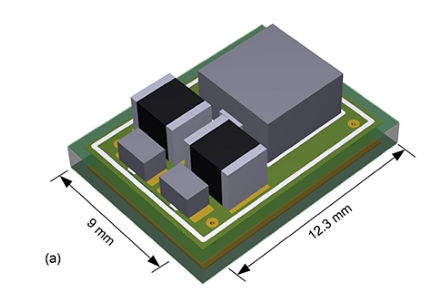
In this case, the advantage of the active filtering is that the overall volume of the active filtering DC/DC solution is mainly because the offset circuit only needs to use a much more passive filter, rather than the larger “pretty” Force “passive filter.

Passive filter
In contrast, the active filter uses a amplifier (computing amplifier) to set the gain and phase of the filter response. Compared with the passive filter, the source filter has many other functional advantages, such as high input impedance and low output impedance, thereby providing good isolation between levels and levels. This greatly simplifies multiple levels of multiple levels to improve the characteristics of the filter. However, the active filter (noun) is still just a positive signal pathway filter without a reverse noise pathway. It is different from active filtering (verb).
LISUN EMI receiver system for EMI (Electromagnetic Interference) radiation conduction or conducted emissions testing. The EMI-9KB EMI receiver is produced by the full closure structure and strong electro-conductibility material, which has high shielding effect. Due to the new technology for the EMI Test System, it solved the instrument self-EMI problem. The test results are according to the international format test report. The EMI Test System EMI-9KB fully meets CISPR15:2018, CISPR16-1, GB17743, FCC, EN55015 and EN55022.

EMI-9KB EMI Test Receiver
How to test EMI Interference?
Electromagnetic disturbance that degrades the performance of electrical equipment or electronic device, works abnormally or fails. It can be divided into conducted interference test and radiated interference test. LISUN EMI-9KB is an automatic EMI receiver system for EMI (Electromagnetic Interference) radiation conduction or conducted emissions testing. It can do both conducted interference test and radiated interference test.

Lisun Instruments Limited was found by LISUN GROUP in 2003. LISUN quality system has been strictly certified by ISO9001:2015. As a CIE Membership, LISUN products are designed based on CIE, IEC and other international or national standards. All products passed CE certificate and authenticated by the third party lab.
Our main products are Goniophotometer, Integrating Sphere, Spectroradiometer, Surge Generator, ESD Simulator Guns, EMI Receiver, EMC Test Equipment, Electrical Safety Tester, Environmental Chamber, Temperature Chamber, Climate Chamber, Thermal Chamber, Salt Spray Test, Dust Test Chamber, Waterproof Test, RoHS Test (EDXRF), Glow Wire Test and Needle Flame Test.
Please feel free to contact us if you need any support.
Tech Dep: Service@Lisungroup.com, Cell/WhatsApp:+8615317907381
Sales Dep: Sales@Lisungroup.com, Cell/WhatsApp:+8618117273997

LISUN’s Motor-Operated Tool | Power Tool Testing solutions strictly comply with a range of core international standards, providing full support for safety and electromagnetic compatibility (EMC)...

LISUN’s transformer test solutions meet IEC 61558-1, IEC 60076-1, IEC 62041 standards. Covering safety, performance, EMC tests, ensuring transformers comply with global requirements.

LISUN’s household and appliance switch testing solutions meet IEC 60669, IEC 61058, IEC 62271 standards. Covering electrical, mechanical & EMC tests for global compliance.

For the CFL design and manufactory, LISUN can supply a full quality control test solution, including photometric, colorimetric, electricity, flicker, IES candela distribution, surge test, electrical...

 中文简体
中文简体