LM-79 Moving Detector Goniophotometer (Mirror Type C)
LSG-6000

High Precision Rotation Luminaire Goniophotometer
LSG-1890B

High Precision Rotation Luminaire Goniospectroradiometer
LSG-1890BCCD

Goniophotometer for Automotive and Signal Lamps
LSG-1950

Goniophotometer for Traffic Signal Lamps
LSG-1950S

Compact Goniophotometer
LSG-1200A

Near Field Moving Detector Goniophotometer
LSG-1900B
Select an organization
to browse standards
With the development of electronic technology, household electrical products are becoming increasingly popular and electronic, and the increasingly developed radio, television, post and telecommunications and computer networks, and the electromagnetic environment is becoming increasingly complicated and deteriorating, making the electromagnetic compatibility of electronics (EMC electromagnetic interference EMI and Electromagnetic anti -EMS) issues have also been paid attention to by countries and manufacturers. The electromagnetic compatibility (EMC) of electronics and electrical products is a very important quality indicator. It not only does it affect the work reliability and use of the product itself, but also may affect the normal work of other equipment and systems. Protection of the electromagnetic environment. In order to regulate the electromagnetic compatibility of electronic products, all developed countries and some developing countries have formulated electromagnetic compatibility standards. Electromagnetic compatibility standards are the basic requirements that make products work normally in the actual electromagnetic environment. The reason why it is called the basic requirement is that even if the product meets the electromagnetic compatibility standards, interference problems may occur in actual use. Most of the national standards are based on the standards formulated by the International Electricity Commission (IEC).

Introduction for EMI/EMC/EMS
The European Community stipulates that starting from January 1996, all electrical products must pass EMC certification, and it can be sold in the European Community market after adding the CE logo. This move has caused widespread impact in the world, and countries have taken measures to implement mandatory management of EMC performance of electrical electronics. Internationally influence, such as the European Union 2004/108/EC instructions (ie EMC instructions), and the US Federal Code CFR 47/FCC Rules, etc., all made clear requirements for electromagnetic compatibility certification
The full name of EMC is electromagnetic compatibility that defines “the ability of equipment and systems that can work normally in its electromagnetic environment without the ability to constitute an unbearable electromagnetic harassment in the environment.” This definition contains two aspects in two aspects the meaning. First of all, the device should work properly in a certain electromagnetic environment, that is, the device should have a certain degree of electromagnetic resistance (EMS). The impact is electromagnetic harassment (EMI).
The electromagnetic compatibility EMC performance of electronic and electrical products is a very important technical indicator. The EMC phenomenon mainly includes electromagnetic compatibility, electromagnetic harassment, antipity, and electromagnetic interference. Protection of the electromagnetic environment. As a result, the requirements for EMC are also very important conditions for products to enter the international market.
What is electromagnetic compatibility?
Electromagnetic compatibility (EMC) refers to the ability of equipment or systems to meet the required operation in its electromagnetic environment and does not have an unbearable electromagnetic interference in any device in its environment.
Therefore, EMC includes two requirements: on the one hand, it means that the equipment can not exceed a certain limit on the electromagnetic interference generated by the environment during the normal operation; on the other hand, it means the degree of antipity, that is, electromagnetic sensitivity.
For engineers designing LED power, electromagnetic interference should be a key issue that has always existed in design. However, people who are familiar with the design of the power circuit know that in the design of the LED power supply, electromagnetic interference EMI is a big problem. So how can we solve this problem?
First of all, let’s take a look at several factors that can affect EMI/EMC: the circuit structure that drives the power supply; the switching frequency, grounding, PCB design, and smart LED power reset circuit design. Since the initial LED power supply is a linear power supply, the linear power supply consumes a lot of energy in the form of heat when working. The working method of a linear power supply allows him to have a pressure device from a high voltage and low voltage. Generally, the transformer is generally transformer, and then the DC voltage is output through the rectifier. Although it is bulky, the heat is large, the advantage is that the external interference is small, the electromagnetic interference is small, and it is also easy to solve. And now the more LED switching power supply is used in PWM, the LED driver power supply is to allow the power crystal tube to work in the state of diverting and turning off. During the turnover, the voltage is low, the current is large; the voltage is high, the current is small, and the current is small, so the loss generated on the power semiconductor device is also small. The disadvantages are more obvious that electromagnetic interference (EMI) is also more serious.
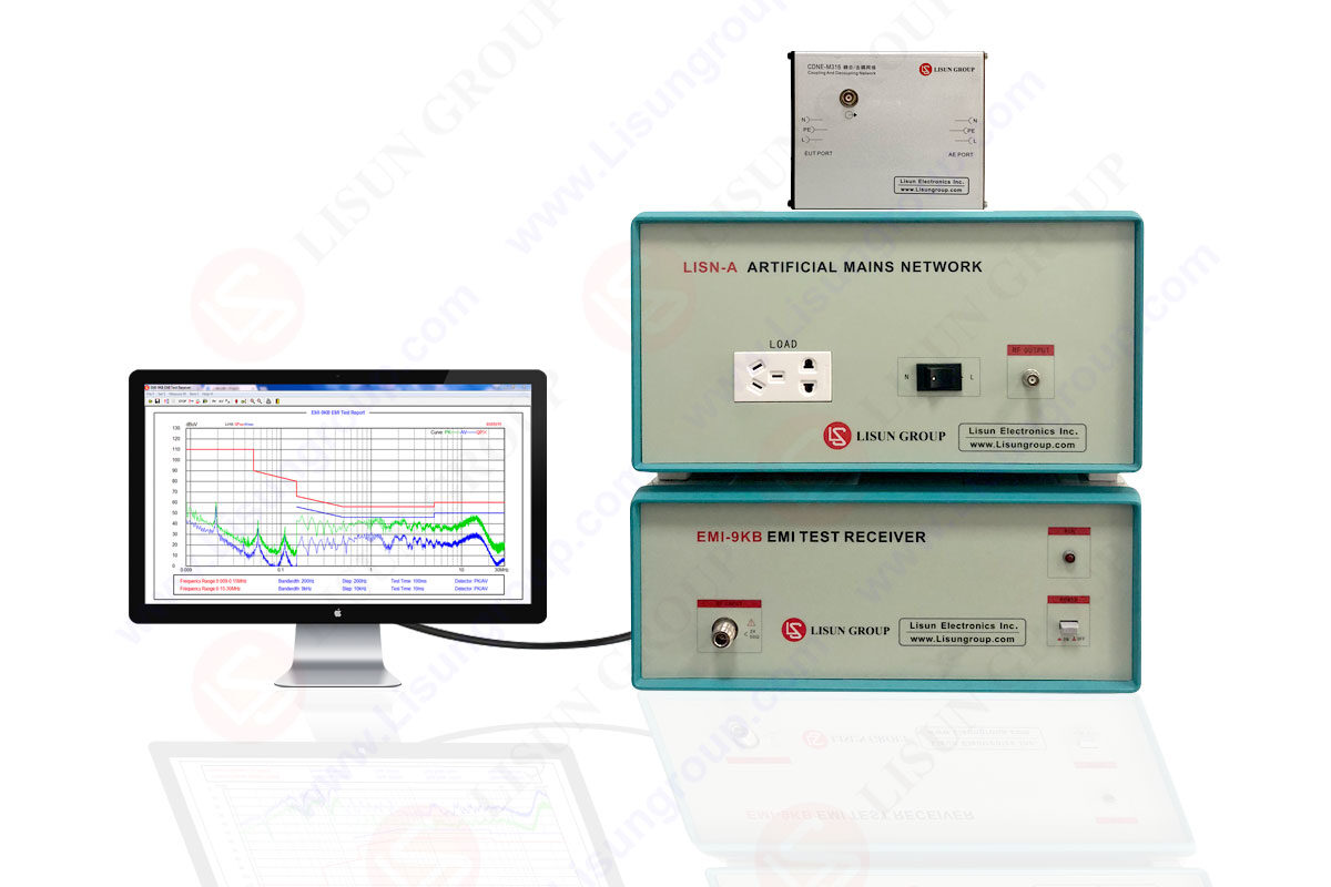
LISUN EMI-9KB EMI receiver is produced by the full closure structure and strong electro-conductibility material, which has high shielding effect. Due to the new technology for the EMI Test System, it solved the instrument self-EMI problem. The test results are according to the international format test report. The EMI Test System EMI-9KB fully meets CISPR15:2018, CISPR16-1, GB17743, FCC, EN55015 and EN55022.

EMI-9KB EMI Test Receiver
There are roughly two ways of transmission of electromagnetic harassment: one is conduction interference, and the other is radiation interference. The upper -type noise filter for improving the noise tolerance of the circuit can be designed to work under a frequency band within a frequency band of 9kHz to 1GHz (according to the relevant standards of electromagnetic compatibility). In general, it can be considered that the low -noise frequency manifests as conduction interference (harassment), and noise filter mainly depends on the demeiing circle to provide noise inhibition; at the high -end noise frequency, the conduction of noise power is absorbed and distributed capacitance by the other effect resistance of the clutter circle. Wingrser, at this time, radiation harassment has become the main form of interference. Radiation harassment of the noise current on nearby components and the inferiority, which will cause self -excitation in severe cases, which becomes more prominent in the assembly of small high -density circuit components. Most anti -EMI devices are used as low -pass filter inserting circuits to inhibit or absorb noise interference. Design or select the filter delay frequency according to the noise frequency of need. It has been mentioned above that the noise filter is inserted into the circuit as a noise loser. Its role is to be seriously lost to noise higher than the frequency of signal. With the concept of noise loss, the role of the filter can be understood in this way: through noise filter, noise or due to pressure (attenuation) to reduce the noise output level; or absorb noise power due to multiple reflection; The oscillating conditions improve the noise tolerance of the circuit. In addition, the following problems should be paid attention to design and use anti -EMI devices:
(1) Understand the electromagnetic environment, and choose the frequency range reasonably;
(2) Whether there is a DC or strong communication in the circuit where the noise filter is located to prevent the magnetic heart saturation failure of the device;
(3) Understand the impedance and properties of the front and rear impedance of the inserting circuit to achieve the noise loss. The stiffened ring impedance is generally 30-500Ω.
(4) Pay attention to distributed capacitors, adjacent components and wires to generate emotional disturbance;
(5) Control device temperature rise, generally do not exceed 60 ° C.
In essence, the requirements for EMC instructions are very simple. It basically indicates that the product must not emit unnecessary electromagnetic pollution (interference), and because there is a certain amount of electromagnetic pollution in the environment, the product must be able to avoid the influence of the reasonable quantity. The instruction itself does not give a number or guide that needs to be transmitted or antipylocked, nor does it indicate that frequency band restrictions are not given. So, what test requirements are when the product does EMC test?
EMC contains two major items: EMI (interference) and EMS (sensitivity, anti -interference)
EMI test items include: RE (radiation launch), CE (conduction interference), Harmonic (harmonic), FLICKER (flashing)
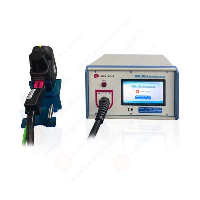
EMS test items include: ESD (electrostatic)
Lisun Instruments Limited was found by LISUN GROUP in 2003. LISUN quality system has been strictly certified by ISO9001:2015. As a CIE Membership, LISUN products are designed based on CIE, IEC and other international or national standards. All products passed CE certificate and authenticated by the third party lab.
Our main products are Goniophotometer, Integrating Sphere, Spectroradiometer, Surge Generator, ESD Simulator Guns, EMI Receiver, EMC Test Equipment, Electrical Safety Tester, Environmental Chamber, Temperature Chamber, Climate Chamber, Thermal Chamber, Salt Spray Test, Dust Test Chamber, Waterproof Test, RoHS Test (EDXRF), Glow Wire Test and Needle Flame Test.
Please feel free to contact us if you need any support.
Tech Dep: Service@Lisungroup.com, Cell/WhatsApp:+8615317907381
Sales Dep: Sales@Lisungroup.com, Cell/WhatsApp:+8618117273997

LISUN’s Motor-Operated Tool | Power Tool Testing solutions strictly comply with a range of core international standards, providing full support for safety and electromagnetic compatibility (EMC)...

LISUN’s electric toy testing solutions cover IEC 62115, EN 71-1, ASTM F963 standards. Including electrical, mechanical, flammability tests to ensure toy safety compliance globally.

LISUN’s transformer test solutions meet IEC 61558-1, IEC 60076-1, IEC 62041 standards. Covering safety, performance, EMC tests, ensuring transformers comply with global requirements.

LISUN’s energy meter testing solutions align with IEC 62052-11, IEC 62053 series standards. Covering safety, electrical, environmental, and EMC tests, we help manufacturers meet global compliance...

LISUN’s household and appliance switch testing solutions meet IEC 60669, IEC 61058, IEC 62271 standards. Covering electrical, mechanical & EMC tests for global compliance.
LISUN’s automotive electronics test solutions cover photometric/colorimetric testing, EMC immunity tests, IP waterproof/dustproof tests, and environmental simulation, meeting ISO, SAE, ECE standards.
LISUN has all equipment according to the IEC60669 measurement, including environmental chamber, IP code waterproof dustproof test, switch lift test, etc.

Lisun can supply full test solutions for fluorescent lamp, including integrating sphere system, goniophotometer system, EMI EMC test, electronic ballast tester, electrical safety test, etc.

For the CFL design and manufactory, LISUN can supply a full quality control test solution, including photometric, colorimetric, electricity, flicker, IES candela distribution, surge test, electrical...

LISUN’s LED driver test solutions cover lab testing, online testing, EMC/EMI tests, and safety checks, meeting IEC 60335, UL 60335 standards for reliable performance evaluation.

 中文简体
中文简体