LM-79 Moving Detector Goniophotometer (Mirror Type C)
LSG-6000

High Precision Rotation Luminaire Goniophotometer
LSG-1890B

High Precision Rotation Luminaire Goniospectroradiometer
LSG-1890BCCD

Goniophotometer for Automotive and Signal Lamps
LSG-1950

Goniophotometer for Traffic Signal Lamps
LSG-1950S

Compact Goniophotometer
LSG-1200A

Near Field Moving Detector Goniophotometer
LSG-1900B
Select an organization
to browse standards
Abstract
In the actual operating environment of electrical and electronic equipment, high-energy transient interference caused by natural lightning induction and large-capacity inductive-capacitive load switching poses a serious threat to the stable operation of equipment power cords and internal connecting wires. As a core testing device, the surge generator working principle can simulate such interference scenarios and provide a unified, standardized basis for evaluating the tolerance of different equipment. This paper takes the LISUN SG61000-5 Surge Generator Working Principle as the research object, combined with the IEC61000-4-5 international standard, and analyzes from the aspects of the device’s working principle, technical parameters, testing process and practical application cases. It intuitively presents its performance advantages and testing effects through table data, aiming to clarify the key role of the surge generator working principle in ensuring the reliability of electrical and electronic equipment.
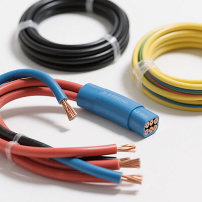
With the rapid development of industrial automation, communication technology and consumer electronics industry, electrical and electronic equipment have increasingly higher requirements for the stability of the operating environment. However, natural lightning events will generate instantaneous high voltage and large current in equipment power cords and signal lines through electromagnetic induction; at the same time, the operation of large-capacity inductive-capacitive loads such as the start-stop of large motors in factory workshops and the switching of capacitor compensation cabinets in power systems will also cause transient interference such as sudden voltage rise and fall in the power grid. If such interference exceeds the equipment’s tolerance limit, it may cause equipment crash and data loss in mild cases, and component burnout and system paralysis in severe cases.
To solve this problem, the International Electrotechnical Commission (IEC) has formulated the IEC61000-4-5 standard “Electromagnetic Compatibility – Part 4-5: Testing and Measurement Techniques – Surge (Impact) Immunity Test”, which unifies the testing methods and evaluation indicators for high-energy transient interference. As a core device meeting this standard, the surge generator working principle can accurately simulate the transient waveforms generated by lightning induction and load switching, and provide a common basis for the tolerance testing of power cords and internal connecting wires of different types of equipment (such as communication base stations, household appliances, automotive electronic components, etc.), thus becoming an indispensable tool in the links of equipment research and development, production and quality inspection.

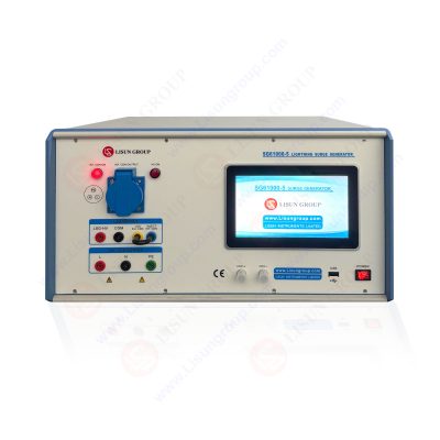
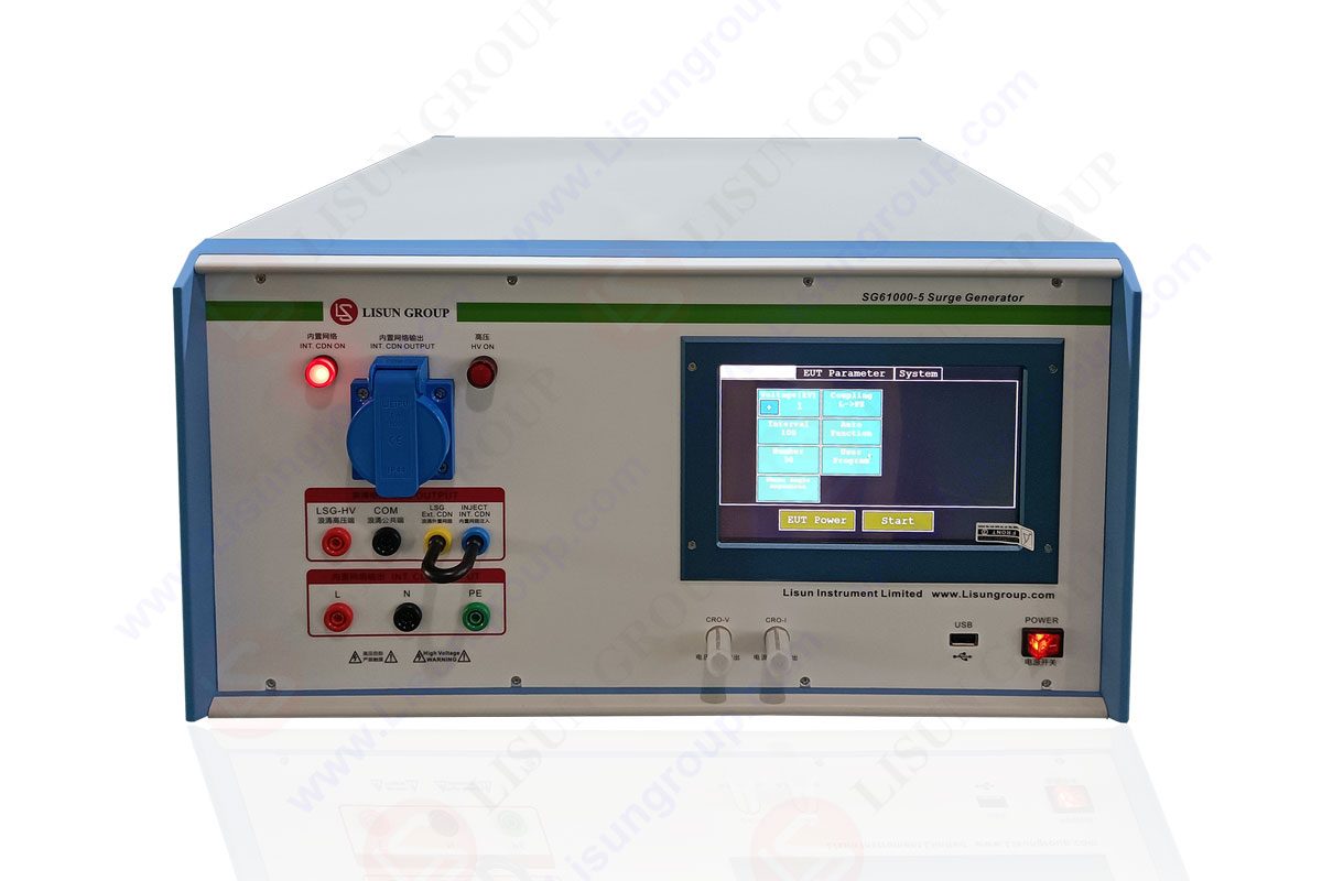
Surge Generator SG61000 5
The core function of the surge generator working principle is to generate transient pulse waveforms that meet the standards, and its working process is mainly divided into three stages: energy storage, waveform modulation and pulse injection:
• Energy Storage Stage: The device charges the internal large-capacity capacitor through a high-voltage DC power supply, and adjusts the charging voltage according to the testing requirements to achieve the storage of different energy levels (the energy calculation formula is
where $C$ is the capacitance value and $V$ is the charging voltage).
• Waveform Modulation Stage: When the capacitor discharges, the RLC damping circuit composed of inductors and resistors is used to modulate the rise time, peak duration and attenuation characteristics of the pulse, so as to ensure that the output waveform meets the provisions of the IEC61000-4-5 standard. For example, the 1.2/50μs voltage waveform (rise time 1.2μs, half-peak time 50μs) and 8/20μs current waveform (rise time 8μs, half-peak time 20μs) for power cord testing are realized by accurately matching the circuit parameters.
• Pulse Injection Stage: The modulated transient pulse is injected into the power cord or internal connecting wire of the Equipment Under Test (EUT) through a Coupling/Decoupling Network (CDN), while preventing the pulse from interfering with the power grid or other testing equipment.
The IEC61000-4-5 standard provides clear technical specifications for surge testing, mainly including the following three aspects:
• Waveform Requirements: The standard specifies two core waveform types. One is the 1.2/50μs voltage waveform (open-circuit state) and 8/20μs current waveform (short-circuit state) used to simulate lightning induction; the other is the 10/700μs voltage waveform and 5/320μs current waveform for long-distance transmission line interference. The surge generator working principle should be able to accurately generate these waveforms, and the waveform parameter error should be controlled within ±20%.
• Testing Levels: According to the electromagnetic interference intensity of the equipment’s use environment, the standard divides the testing levels into Level 1-4 and Level X (special customization). The corresponding voltage and current peaks of each level are shown in the following table:
| Testing Level | Voltage Peak (kV) | Current Peak (kA) | Application Environment |
| Level 1 | 0.5 – 1 | 0.25 – 0.5 | Well-shielded control rooms, laboratories |
| Level 2 | 1 – 2 | 0.5 – 1 | General industrial environments, indoor equipment |
| Level 3 | 2 – 4 | 1 – 2 | Outdoor equipment, unshielded industrial environments |
| Level 4 | 4 – 6 | 2 – 3 | Lightning-prone areas, unshielded outdoor equipment |
| Level X | Customized | Customized | Special scenarios (such as aerospace equipment) |
• Testing Configuration: The standard requires that the testing system should include a surge generator working principle, a Coupling/Decoupling Network (CDN), a grounding system and monitoring equipment. Among them, the CDN should realize the effective coupling between the pulse and the EUT, and isolate the EUT from the power grid to avoid interference diffusion; the grounding system should meet the impedance ≤ 0.5Ω to ensure the safe discharge of pulse energy.
The LISUN SG61000-5 Surge Generator Working Principle is a high-performance testing device that fully meets the IEC61000-4-5 standard, and its technical parameters and functional design fully meet the tolerance testing requirements of equipment in different industries.
The key technical parameters of this device are shown in the following table. Its output range covers the testing requirements of Level 1-4, with high waveform accuracy and strong stability:
| Technical Parameter | Index Range | Accuracy Requirement |
| Voltage Waveform (Open-Circuit) | 1.2/50μs | ±20% |
| Current Waveform (Short-Circuit) | 8/20μs | ±20% |
| Output Voltage Range | 0 – 10kV (0 – 20kV optional) | ±5% |
| Output Current Range | 0 – 5kA (0 – 10kA optional) | ±5% |
| Pulse Polarity | Positive/Negative/Alternating | – |
| Pulse Interval | 10ms – 100s | Adjustable |
| Stored Testing Programs | 100 groups | – |
| Communication Interface | RS232/Ethernet | Support remote control |
• Multi-Scenario Adaptability: The device supports three output impedances of 2Ω, 12Ω and 500Ω, which can correspond to the testing requirements of power cords (2Ω/12Ω) and signal lines (500Ω) respectively. No additional hardware replacement is required, which reduces the testing cost.
• Intelligent Operation Experience: It is equipped with a 7-inch touch screen, supporting one-click parameter setting, real-time waveform display and testing data storage; at the same time, it provides PC-side control software, which can realize the linkage of multiple devices and automatic generation of testing reports, improving the testing efficiency.
• Safety Protection Design: It has built-in over-voltage, over-current and over-temperature protection circuits, which automatically cut off the power supply when the device is abnormal; the shell is made of flame-retardant materials, and the grounding terminal meets the safety standards, ensuring the safety of operators and equipment.
Taking the LISUN SG61000-5 Surge Generator Working Principle as an example, combined with the IEC61000-4-5 standard, the tolerance testing process of equipment power cords and internal connecting wires can be divided into the following five steps:
4.1 Testing Preparation
Equipment Connection: Connect the surge generator working principle to the power cord of the Equipment Under Test (EUT) through a Coupling/Decoupling Network (CDN), and connect the EUT to the load according to the actual working state; at the same time, connect monitoring equipment (such as oscilloscopes, power analyzers) to observe the voltage, current response and operating state of the EUT.
Parameter Setting: Determine the testing level according to the use environment of the EUT (for example, select Level 3 for outdoor communication equipment), and set the corresponding voltage/current peak (such as 2kV voltage and 1kA current for Level 3), pulse polarity (5 tests for positive and negative respectively) and pulse interval (1 minute per test to avoid EUT overheating) on the generator.
4.2 Pre-Testing
Inject 1-2 low-energy pulses (such as 50% of the testing level) to check whether the connection of the testing system is normal, whether the monitoring equipment can accurately collect data, and whether the EUT is in a normal working state. If there is loose connection or data abnormality, adjustments should be made in time before restarting.
4.3 Formal Testing
Inject transient pulses according to the set parameters, and observe the operating state of the EUT after each pulse:
Normal Function: The EUT has no phenomena such as crash, data loss and performance degradation;
Temporary Performance Degradation: The EUT has temporary functional abnormalities, but automatically recovers after the pulse ends;
Functional Failure: The EUT has permanent faults, such as component burnout and failure to start.
4.4 Data Recording and Analysis
Record the state of the EUT after each pulse injection, obtain the voltage peak, current peak of the power cord and the transient response data of the internal connecting wires through the monitoring equipment, and compare with the “normal equipment operation” judgment indicators in the IEC61000-4-5 standard (such as voltage fluctuation ≤ 10%, no permanent damage) to evaluate the tolerance level of the EUT.
4.5 Testing Report Generation
Organize the testing data, and generate a report including the testing equipment model, standard basis, parameter settings, EUT state records and tolerance conclusions, which provides a basis for equipment research and development improvement or quality certification.

5. Practical Application Cases
5.1 Tolerance Testing of Communication Base Station Equipment Power Cords
A communication equipment manufacturer used the LISUN SG61000-5 Surge Generator Working Principle to conduct tolerance testing on the newly developed 5G base station power module. The testing level was Level 3 (meeting the requirements of outdoor environment), and the specific data are shown in the following table:
|
Testing Item |
Testing Parameters |
EUT State |
Conclusion |
|
Positive Polarity Pulse Testing |
2kV voltage, 1kA current, 5 times |
Normal for the first 3 times, temporary power failure in the 4th time |
Need to optimize the over-voltage protection circuit |
|
Negative Polarity Pulse Testing |
2kV voltage, 1kA current, 5 times |
All normal |
Good tolerance to negative polarity |
|
Retest after Optimization (Positive Polarity) |
2kV voltage, 1kA current, 5 times |
All normal |
Tolerance up to standard |
Analysis: In the initial stage of testing, the EUT had a temporary power failure. After investigation, it was found that the trigger threshold of the over-voltage protection circuit in the power module was too low. After adjusting the parameters of the protection circuit, the equipment could stably withstand Level 3 transient interference, meeting the outdoor operation requirements of the base station.
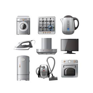
5.2 Testing of Internal Connecting Wires of Household Appliances
A home appliance enterprise used this generator to conduct Level 2 testing (indoor environment) on the internal motor connecting wires of washing machines. The testing results are shown in the following table:
|
Testing Times |
Pulse Polarity |
Voltage Peak (kV) |
Current Peak (kA) |
State of Connecting Wires |
|
1 |
Positive |
1.5 |
0.75 |
Normal |
|
2 |
Positive |
1.5 |
0.75 |
Normal |
|
3 |
Negative |
1.5 |
0.75 |
Normal |
|
4 |
Negative |
1.5 |
0.75 |
Normal |
|
5 |
Alternating |
1.5 |
0.75 |
Normal |
Conclusion: The internal connecting wires of the washing machine can withstand Level 2 high-energy transient interference, and no design improvement is needed.
6. Conclusion and Prospect
As a core tool for evaluating the tolerance of equipment power cords and internal connecting wires to high-energy transient interference, the surge generator working principle provides a unified basis for the performance evaluation of equipment in different industries and types with its standardized testing capabilities. The LISUN SG61000-5 Surge Generator Working Principle shows significant advantages in the testing of communication, home appliances, automotive electronics and other fields due to its technical parameters meeting the IEC61000-4-5 standard, multi-scenario adaptability and intelligent operation design.

LISUN’s Motor-Operated Tool | Power Tool Testing solutions strictly comply with a range of core international standards, providing full support for safety and electromagnetic compatibility (EMC)...

LISUN’s electric toy testing solutions cover IEC 62115, EN 71-1, ASTM F963 standards. Including electrical, mechanical, flammability tests to ensure toy safety compliance globally.

LISUN’s transformer test solutions meet IEC 61558-1, IEC 60076-1, IEC 62041 standards. Covering safety, performance, EMC tests, ensuring transformers comply with global requirements.

LISUN’s energy meter testing solutions align with IEC 62052-11, IEC 62053 series standards. Covering safety, electrical, environmental, and EMC tests, we help manufacturers meet global compliance...

LISUN’s household and appliance switch testing solutions meet IEC 60669, IEC 61058, IEC 62271 standards. Covering electrical, mechanical & EMC tests for global compliance.
LISUN’s cable and wire test solutions meet IEC 60245-1, IEC 60227-1, IEC 60502-1 and IEC 60189 standards, covering electrical, mechanical, and safety tests for global compliance.
LISUN has all equipment according to the IEC60669 measurement, including environmental chamber, IP code waterproof dustproof test, switch lift test, etc.

Lisun can supply full test solutions for fluorescent lamp, including integrating sphere system, goniophotometer system, EMI EMC test, electronic ballast tester, electrical safety test, etc.

For the CFL design and manufactory, LISUN can supply a full quality control test solution, including photometric, colorimetric, electricity, flicker, IES candela distribution, surge test, electrical...

LISUN’s LED driver test solutions cover lab testing, online testing, EMC/EMI tests, and safety checks, meeting IEC 60335, UL 60335 standards for reliable performance evaluation.

 中文简体
中文简体