LM-79 Moving Detector Goniophotometer (Mirror Type C)
LSG-6000

High Precision Rotation Luminaire Goniophotometer
LSG-1890B

High Precision Rotation Luminaire Goniospectroradiometer
LSG-1890BCCD

Goniophotometer for Automotive and Signal Lamps
LSG-1950

Goniophotometer for Traffic Signal Lamps
LSG-1950S

Compact Goniophotometer
LSG-1200A

Near Field Moving Detector Goniophotometer
LSG-1900B
Select an organization
to browse standards
Electronic noise, also known as electromagnetic interference, impedes cable communications and weakens their integrity. Typically, machinery and motors that emit electromagnetic radiation serve as EMI receiver generators. Conducted interference and radiated interference are the two forms of EMI receivers. The coupling of signals from one electrical network to another electrical network over a conductive medium is referred to as conducted interference. When a signal from an interference source is coupled by another electrical network via space, it is said to be radiating interference.

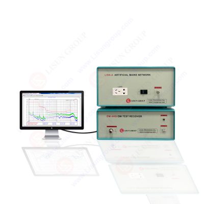
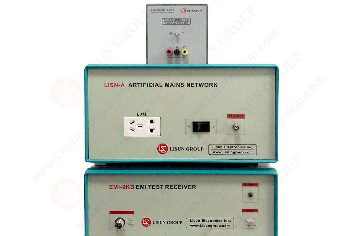
EMI-9KB EMI Test Receiver
Testing interference using EMI Receivers
Electromagnetic interference causes electrical or electronic equipment to function poorly, act erratically, or fail. It can be separated into tests for radiation interference and conducted interference. The LISUN EMI-9KB is an automatic EMI receiver system which is used for conducting emissions testing or EMI radiation testing. This article will explore what EMC test equipment you need for conducting interference tests.
Applications and range of test frequency for emission testing
Automotive onboard applications components and modules are tested in accordance with CISPR 25 across a total frequency range of 150 kHz to 2.5 GHz.
For items produced for ISM applications, testing in CISPR bands C and D across a frequency range of 30 MHz to 1 GHz in accordance with CISPR 11’s scope satisfies the RE criteria. The intended installation environment for the equipment determines whether the tests in CISPR 11 are applicable.
Radiated emission requirements are met in accordance with MIL-STD-461G by performing RE101 (magnetic field) and RE102 (electric field) tests in the frequency ranges of 30 Hz to 100 kHz and 10 kHz to 18 GHz, respectively. These tests make sure that the magnetic and electric field emissions from the equipment being tested (EUT) and the cables that are connected to it do not go above the allowed limits.
EMI test equipment
An EMI receiver or spectrum analyzer with the proper peak, quasi-peak, or average detector, as stated in CISPR 16-1-1, are among the main test tools needed to conduct radiated emission tests. A line impedance stabilization network (LISN) or artificial network (AN) offers a clear and consistent impedance (very close to 50) across the EUT power terminals over the relevant test frequency range.

EMI Test Receiver
A number of antennas, such as a magnetic field probe for the RE101 test, a monopole rod antenna for the RE102 and CISPR 25 tests, and biconical and double-ridge guiding horn antennas. The measurement receiver needs to have the suitable resolution bandwidth (RBW ) specified in the relevant standards for the various applications in order to sweep the requisite test frequency range.
Test setup requirements
Antenna types
CISPR 25 calls for antennas with a nominal 50- output impedance that are linearly polarized rod, log-periodic, biconical, and horn antennas to span a range of frequencies from 150 kHz to 2.5 GHz. Broadband biconical and horn antennas are used by CISPR 11 to detect radiated emission disturbances from 30 MHz to 18 GHz. For RE101 from 30 Hz to 100 kHz, MIL-STD-461 employs a magnetic field loop sensor, and for RE102 from 10 kHz to 18 GHz, it uses rod, biconical, and horn antennas. In general, measurements with both horizontal and vertical antenna polarizations are necessary for specifications above 30 MHz.
Antenna distances
CISPR 11 calls for 3 m, 10 m, or 30 m depending on the test location, the equipment group and class designation. Furthermore, both CISPR 25 and MIL-STD-461 RE102 mention an antenna distance of 1 m. In order to conduct the MIL-STD-461 RE101 test, a loop antenna must be placed 7 cm away from the EUT and a magnetic field measurement at frequencies as low as 30 Hz is required. A magnetic field measurement for group 2 equipment between 150 kHz and 30 MHz is also included in CISPR 11.
Receiver detector types
PK or QP and AV detectors are used in CISPR 25. QP and AV detectors are used by CISPR 11, and a PK detector is required by MIL-STD-461 for RE tests.
Reference ground plane
The ground plane, which is the top metallic surface on the test bench or table that electrically bonds to the walls or floor of the shielded enclosure such that its DC resistance does not exceed 2.5 m, is made of copper, brass, bronze, or galvanized steel. According to the publications CISPR 25, CISPR 11, and MIL-STD-461, the minimum ground plane diameters for RE measurements are given as 2 m by 1 m, 2 m by 2 m, and 2.25 m2, respectively.
EUT and LISN placement
To achieve a height of 50 mm above the reference ground plane, the EUT for CISPR 25 mounts on a nonconductive, low relative permittivity material, such as plastic foam or wood. 800 mm above the ground plane is the CISPR 11 table-mounted arrangement. If the EUT is bonded during installation, it must also be bonded to the ground plane. On the ground plane, the LISN is mounted and electrically connected to it.
Placement and length of power cables
For CISPR 25 and MIL-STD-461, the power leads that connect the EUT to the LISN power port are positioned 50 mm above the reference ground plane over a nonconductive support material with a low relative permittivity of 1.4. The loop areas available for coupling and parasitic capacitances from switching nodes to the ground plane are standardized by the 50-mm standoff.
The first 2 m of each interconnecting cable connected to each EUT enclosure for MIL-STD-461 are routed parallel to the setup’s front boundary to guarantee that RE testing accurately evaluates the EUT’s performance.
According to the CISPR 25, CISPR 11, and MIL-STD-461 documents, the power leads have lengths of 1.5 m, 1 m, and 2 m, respectively.
Conclusion
If you set up your EMI testing equipment according to these guidelines, you can efficiently conduct EMI testing on your product.
Lisun Instruments Limited was found by LISUN GROUP in 2003. LISUN quality system has been strictly certified by ISO9001:2015. As a CIE Membership, LISUN products are designed based on CIE, IEC and other international or national standards. All products passed CE certificate and authenticated by the third party lab.
Our main products are Goniophotometer, Integrating Sphere, Spectroradiometer, Surge Generator, ESD Simulator Guns, EMI Receiver, EMC Test Equipment, Electrical Safety Tester, Environmental Chamber, Temperature Chamber, Climate Chamber, Thermal Chamber, Salt Spray Test, Dust Test Chamber, Waterproof Test, RoHS Test (EDXRF), Glow Wire Test and Needle Flame Test.
Please feel free to contact us if you need any support.
Tech Dep: Service@Lisungroup.com , Cell/WhatsApp:+8615317907381
Sales Dep: Sales@Lisungroup.com , Cell/WhatsApp:+8618117273997

LISUN’s Motor-Operated Tool | Power Tool Testing solutions strictly comply with a range of core international standards, providing full support for safety and electromagnetic compatibility (EMC)...

LISUN’s transformer test solutions meet IEC 61558-1, IEC 60076-1, IEC 62041 standards. Covering safety, performance, EMC tests, ensuring transformers comply with global requirements.

LISUN’s household and appliance switch testing solutions meet IEC 60669, IEC 61058, IEC 62271 standards. Covering electrical, mechanical & EMC tests for global compliance.

LISUN provide full test solutions for HID lamp, including integrating sphere system, goniophotometer system, EMI EMC chamber, HID ballast tester, electrical safety test, etc.

Lisun can supply full test solutions for fluorescent lamp, including integrating sphere system, goniophotometer system, EMI EMC test, electronic ballast tester, electrical safety test, etc.

For the CFL design and manufactory, LISUN can supply a full quality control test solution, including photometric, colorimetric, electricity, flicker, IES candela distribution, surge test, electrical...

 中文简体
中文简体