
LM-79 Moving Detector Goniophotometer (Mirror Type C)
LSG-6000

High Precision Rotation Luminaire Goniophotometer
LSG-1890B

High Precision Rotation Luminaire Goniospectroradiometer
LSG-1890BCCD

Goniophotometer for Automotive and Signal Lamps
LSG-1950

Goniophotometer for Traffic Signal Lamps
LSG-1950S

Compact Goniophotometer
LSG-1200A

Near Field Moving Detector Goniophotometer
LSG-1900B
Select an organization
to browse standards
Electromagnetic interference is one of the most difficult problems to solve when producing an electronic device. It is also known as EMI. The influence of these inevitable interferences on the instrument’s performance need to be carefully monitored.
This is done to comprehend and quantify the electromagnetic compatibility of the instrument under test. Efforts are made to lessen the impact of these undesirable interferences so that the equipment can be used in the actual world. This can be done using EMI receivers. This article will look at EMI measurement techniques.
EMI receivers are high-performance equipment. These are used for data collection. EMI receivers are useful in situations where transitory signals may arise and quick achievement rates are necessary. An example is an EMC test chamber. Electromagnetic Interference is the electronic noise that interferes with cable transmissions. There are two types of Electromagnetic Interference. These are conducted interference and radiated interference.
The EMI standard was devised to protect electronic circuits from electromagnetic interference that could cause them to fail to work as intended. These interferences may cause the device to malfunction. This can be to the point where it becomes unsafe for users.

EMI receivers comply with international standards. They are in compliance with ISO and IEC standards. The EMI Test System produced by LISUN meets the EMI-9KB.15:2018, CISPR16-1, GB17743, FCC, EN55015, and EN55022 principles.
The EMI standard is a subset of the Electromagnetic Compatibility standard. EMC is a regulatory standard. It contains a list of performance standards that devices must achieve. This demonstrates that they can coexist with other devices. It also shows that they can work as intended without compromising the other devices’ performance.
EMI measurement techniques include compliance testing and pre-compliance testing. All pre-compliance settings must closely resemble the compliance test setup. This is in terms of hardware, software, and approach used.
There are three key components that aid in the occurrence of EMI. These are the emitter that functions as the source of undesired interferences. The receiver that reacts to these interferences. Last is the coupling channel that carries the interference from the source to the receiver. There are two main kinds of EMI measurement techniques. These are emission testing and immunity testing.

EMI receiver
Nearly every electronic instrument operates as an electromagnetic polluter. This is because of its intentional or unintentional conducted or radiated emissions. These undesired emissions come from power cables, wires, resistors, capacitors, and other components.
They can reach GHz frequencies. In the case of conducted emission they are transmitted through ac power systems. In the case of radiated emission they are transmitted through antennas. Every electronic equipment must undergo emission testing.
This is to keep the electromagnetic environment clean and useable for other allowed purposes. The equipment under test is the emitter in these types of tests. Emission testing can be done for both radiated and conducted emissions. EMI occurs as a result of conducted emission if the coupling channel is inherently conducting. Radiated emission occurs when the coupling channel is of the radiating kind.
The frequency range of 30 MHz–1 GHz is used for standard radiated emission testing. Corresponding wavelengths are 10 m and 0.3 m respectively. One of the most frequent approaches for radiated emission testing for large instruments is an open area test site.
This type of setup typically consists of a theoretically infinite metallic ground plane. A receiving antenna connected to an EMI receiver or spectrum analyzer via cables. And the EUT that is typically kept at a distance of 3 m or 10 m from the receiver.
The distance between the EUT’s nearest exterior surface and the reception antenna is measured. The EUT and receiver are separated by such a considerable distance to ensure that measurements are conducted in the far field region. In this region the radiated field is more stable than in the close field.
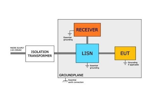
Conducted emission testing is used to determine the noise emitted through the power lead into loaded devices. This noise is emitted as a result of a sudden change in voltage or current in the equipment’s circuitry.
The unwanted noise may have a deadly effect on the linked devices. This can cause the equipment to malfunction. The most common ways for doing emission testing are Line impedance stabilization network, 1X method, probes and TEM cell.
Emission testing and immunity testing are opposites. Noise coming from the EUT was measured during emission testing. Immunity testing refers to the process of exposing the EUT to an electromagnetically hostile environment.
Then you determine whether or not the EUT’s performance has changed. The operation of the EUT are monitored for changes. These changes are then quantified and compared to international or national standards.
An instrument will be unable to function effectively in the actual world if it fails to pass these standards. Techniques used in immunity measures for pre-compliance or compliance EMI testing are continuous and transitory testing.
Continuous immunity testing is used to see if the EUT will work well when it is exposed to continuous noise sources. These include solar radiation, broadcast stations, motor vehicles, and magnetic fields. Continuous source immunity testing is performed for either a few or several minutes.
Transient sources of electromagnetic interference include lightning, electrostatic discharge, voltage fluctuations and quick switching. They can have a devastating effect on system performance. Electronic devices on board an airplane or spaceship are effected by EMI. The meteorology equipment needed to monitor storms, tornadoes, and other natural disasters are also victims of transient EMI.
This makes it important to check the system’s tolerance for these events. A system’s immunity to them is tested in the temporal domain. This is because transient sources emit a considerable amount of EM radiation for a short period of time (a few milliseconds or less).
Lisun Instruments Limited was found by LISUN GROUP in 2003. LISUN quality system has been strictly certified by ISO9001:2015. As a CIE Membership, LISUN products are designed based on CIE, IEC and other international or national standards. All products passed CE certificate and authenticated by the third party lab.
Our main products are Goniophotometer, Integrating Sphere, Spectroradiometer, Surge Generator, ESD Simulator Guns, EMI Receiver, EMC Test Equipment, Electrical Safety Tester, Environmental Chamber, Temperature Chamber, Climate Chamber, Thermal Chamber, Salt Spray Test, Dust Test Chamber, Waterproof Test, RoHS Test (EDXRF), Glow Wire Test and Needle Flame Test.
Please feel free to contact us if you need any support.
Tech Dep: Service@Lisungroup.com, Cell/WhatsApp:+8615317907381
Sales Dep: Sales@Lisungroup.com, Cell/WhatsApp:+8618117273997

LISUN’s Motor-Operated Tool | Power Tool Testing solutions strictly comply with a range of core international standards, providing full support for safety and electromagnetic compatibility (EMC)...

LISUN’s transformer test solutions meet IEC 61558-1, IEC 60076-1, IEC 62041 standards. Covering safety, performance, EMC tests, ensuring transformers comply with global requirements.

LISUN’s household and appliance switch testing solutions meet IEC 60669, IEC 61058, IEC 62271 standards. Covering electrical, mechanical & EMC tests for global compliance.

For the CFL design and manufactory, LISUN can supply a full quality control test solution, including photometric, colorimetric, electricity, flicker, IES candela distribution, surge test, electrical...

 中文简体
中文简体