
LM-79 Moving Detector Goniophotometer (Mirror Type C)
LSG-6000

High Precision Rotation Luminaire Goniophotometer
LSG-1890B

High Precision Rotation Luminaire Goniospectroradiometer
LSG-1890BCCD

Goniophotometer for Automotive and Signal Lamps
LSG-1950

Goniophotometer for Traffic Signal Lamps
LSG-1950S

Compact Goniophotometer
LSG-1200A

Near Field Moving Detector Goniophotometer
LSG-1900B
Select an organization
to browse standards
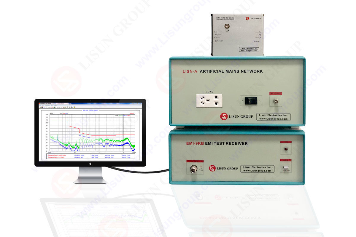
Emissions of electromagnetic radiation are carefully detected by EMI test receivers, which are incredibly precise machines intended to detect such emissions. The LISUN EMI test system (EMI-9KB) may also function as a comprehensive signal and spectrum analyzer.
Designed to make it easy to conduct the tests specified by the Standards for the parameters they describe, including automated test cases.
Description
High-quality instruments like EMI test receivers are necessary to collect data for analysis. It may easily capture transient signals or spurious emissions using an EMI receiver when rapid acquisition rates are required.
It is recommended that an EMI test receiver be used to ensure complete compliance with the requirements given out by organizations such as CISPR, IEC/EN, the FCC, and the MIL-STD when testing for these emissions.
EMI receivers are more trustworthy than spectrum analyzers for doing these tests accurately. There are several things to consider, such as The necessary RBW to collect enough data points over a certain frequency range. Test specifications may specify using a Quasi-peak (QP) detector or a CISPR Average detector.
Filters, a low noise floor, and software that displays pass/fail situations based on predetermined criteria are among the necessary components. When testing in advance of complete compliance being needed, you may choose to rely only on a spectrum analyzer.
Regarding EMI test receivers and EMC analyzers, 2Hz to 44GHz, Advanced Test Equipment Rentals has the finest assortment and best-performing options.

EMI test system
Test Receivers Explored
Given these considerations, it is recommended that a test receiver be used for EMI applications by CISPR, EN, FCC, MIL-STD, and any other relevant standards organizations.
The test standard includes a full list of all possible configurations for the receiver being used in the test, so whatever you decide to configure will be what is measured. This may be seen in action using a standard test receiver configuration.
The operator needs to do nothing more than input the values specified in the standard as test parameters and hit the start button. There must be zero sub-ranging, zero-spanning, and no mental voltage to field strength conversions.
Moreover, it is possible to conduct a compliance test automatically with the help of automated attenuators and preselection. While there are valid reasons for an operator to pause the test, an automated test may provide reliable findings.
Features
The following section delves further into test EMI test receivers by highlighting crucial aspects that show why a test receiver is an ideal instrument for electromagnetic interference (EMI) testing.
Measurement Points
A scanning receiver may take readings from potentially tens of thousands of locations. Compared to a spectrum analyzer’s 500 or 1000-point accuracy, this method provides a far higher degree of precision. In certain MIL-STD contexts, tests with 100,000 measurement points are commonplace.
Tune & Dwell
The second essential function of a scanning receiver is its capacity to tune and linger on a signal. The amount of time a key is held down is known as the dwell time, and it is common practice for infractions to the dwell time criteria of different detectors to be “tagged” as wrong.
EMI Specificity
The availability of EMI-specific features like 6 dB RBW filters, transducer sets, limit lines, and preselector filters, as well as everything else, addressed throughout the spectrum analyzer investigation, all come together in this crucial feature.
Automatic Control
Automatic regulation of selected receiver characteristics is a useful feature of scanning devices. Don’t forget that forcing a spectrum analyzer into a certain mode at the outset might cause it to display false readings.
It’s also true for receivers, albeit it’s far less probable given that an unattended receiver would “take care of itself” if left in auto-control. Typically, RF attenuation, preselection filtering, preamplification settings, RBW settings, and step size are all controlled automatically.
Having these parameters automatically adjusted may prevent most problems for the user. Those settings will be automatically controlled according to the specifications. It is possible to prevent EMI beginners from gathering wrong data and, even worse, basing decisions on poor data by recognizing that no one begins as an expert.
Split-screen display
Like conventional receivers, modern instruments can monitor critical emissions with a numerical display of frequency and level. Analog readings from each detector are shown graphically using separate-colored bars on a single graph.
Emissions may be monitored rapidly and accurately by standards by linking the marker in the overview spectrum to the receiver frequency.
Either previously collected data or a new measurement using the chosen detectors is used to zoom in. When using saved information, it may show all of the information. This is possible because the EMI-9KB receiver may temporarily store up to 250,000 measured data while keeping a single trace active. Since no further measurements are required for a thorough evaluation, this drastically shortens the total measurement time.
Self-test
The integrated self-test allows for module-level fault isolation. Each module has its own correction tables; therefore, it is possible to swap out faulty parts without much readjusting or special equipment. As a result, there is less need for repairs and fewer financial losses caused by them.
High accuracy
The EMI receiver can take readings with an accuracy of 1 dB in the frequency band up to 1 GHz. Individual correction factors recorded on all modules impacting measurement uncertainty allow for this improvement above the 2 dB value specified by CISPR 16-1-1.
The operator may perform procedures to calibrate the instrument’s frequency response, display linearity, and signal path gain correction to guarantee minimal measurement uncertainty in any given configuration.
There is no need for additional hardware like cables thanks to an inherent connection between the necessary calibration sources that allows autocorrection even in system applications. The EMI receiver uses gate arrays and signal processors to perform digitally controlled pulse weighting with the detectors.
Therefore, measurements are more consistent and there is no need to wait for an analog detector to discharge between intervals of measurement. Thus, the duration of measurements is drastically cut down.
Listen, view, measure.
Selecting single frequencies using the markers, tuning the receiver to the marker frequency, and activating the audio path with the in-built AM/FM demodulator via the loudspeaker or headphones are all efficient ways to analyze the spectrum while excluding background noise from sources like sound or TV broadcast transmitters.
Because of the availability of manual pre- or post-measurements and interactive operation, acoustic identification is routinely and effectively used in EMI signal analysis.
EMI receiver requirements in practical applications
With so many types of couplers on the market, it might not be easy to meet everyone’s needs.
Very brief peak voltages of 100 V or more may be generated by LISNs, while antennas, particularly at high frequencies, only generate voltages on the order of several V. A good EMI receiver should resist damage and have a high sensitivity to monitor faint signals.
A further challenge is posed by the fact that disruption signals are always unintended. Their frequency response is often unknown, and it is unclear whether they are stable or unstable. Their spectral intensity may be rather high.
Broadband spectral features are often caused by the pulse nature of the bulk of disturbance signals. Replicability of test findings across labs is crucial in all EMC applications in the event of a disagreement.
Nearly half a century’s worth of EMI measurements has taught us that only using the receiver’s or spectrum analyzer’s frequency range isn’t good enough to get reliable findings.

EMI test system
Differences between receivers and analyzers
Spectrum analyzers that “sweep” through a frequency range adjust the frequency of their instrument’s local oscillator (LO). To cover the whole frequency range of interest, some EMI test receivers use a technique called a “stepped sweep,” in which the instrument is set to a series of fixed frequencies separated by a predetermined amount. The amplitude is recorded for each tuning frequency in case it has to be used later.
Most spectral analyzers that use a sweeping motion do not include a preselection feature. Preselection is an additional layer of filtering implemented at the beginning of the instrument before the first frequency conversion mixing step.
Inadequate dynamic range for quasi-peak (QP) detection during measurements of low repetition frequency pulses is a common cause of inaccurate findings.
You may buy swept spectrum analyzers that have preselection on the market. To ensure complete compliance with CISPR 16-2 and other emissions standards like EN 55011 and EN 55022, these instruments may satisfy all criteria in CISPR 16-1-1.
It’s possible that spectrum analyzers don’t include a preamplifier. Most EMI receivers have a preamplifier after the preselection step, making for a much quieter device. Because of this, EMI receivers may pick up signals that would be lost in the background noise of regular spectrum analyzers.
How to choose an EMI receiver
The decision of what measuring receiver to buy is often influenced by cost, usability, technical requirements, and regulatory compliance (spectrum analyzer or EMI receiver).
CISPR 16 is the primary standard that defines the parameters for EMI receivers, as was mentioned before in this article (Part 1-1: Measuring apparatus). You should get a CISPR 16 compliant EMI receiver if you conducted legally binding emissions testing (along with a fully compliant 3- or 10-Meter chamber).
Such receivers feature the appropriate intermediate frequency (IF) filter bandwidths (6 dB), normal 2 dB absolute amplitude accuracy, detector functions (peak, quasi-peak, and average), dynamic range, and nominal input impedance of 50 ohms; deviations from this value are specified as VSWR (voltage-standing-wave-ratio).
An EMI receiver of this caliber will naturally cost more than a spectrum analyzer that falls short of CISPR 16 standards.
LISUN offers EMI test receivers EMI-9KB that are both compliant and non-compliant. Completely compliant receivers include all the features necessary for certification testing, as outlined in the Standards.
A compliance receiver is a cost-effective option for EMI testing during product development. They use the standard-defined bandwidths, limits, and detectors, but fall short of fully complying with the standards.
The EMI receiver has a hard drive to store the measurement parameters and results. LISUN developed software that allows users to create in-depth reports to ensure EMI compliance.
Network operators and government organizations may take advantage of the portability of the LISUN EMI receiver by measuring field strength on-site or locating sources of disturbance; it is small, lightweight, and can run on batteries.
Lisun Instruments Limited was found by LISUN GROUP in 2003. LISUN quality system has been strictly certified by ISO9001:2015. As a CIE Membership, LISUN products are designed based on CIE, IEC and other international or national standards. All products passed CE certificate and authenticated by the third party lab.
Our main products are Goniophotometer, Integrating Sphere, Spectroradiometer, Surge Generator, ESD Simulator Guns, EMI Receiver, EMC Test Equipment, Electrical Safety Tester, Environmental Chamber, Temperature Chamber, Climate Chamber, Thermal Chamber, Salt Spray Test, Dust Test Chamber, Waterproof Test, RoHS Test (EDXRF), Glow Wire Test and Needle Flame Test.
Please feel free to contact us if you need any support.
Tech Dep: Service@Lisungroup.com, Cell/WhatsApp:+8615317907381
Sales Dep: Sales@Lisungroup.com, Cell/WhatsApp:+8618117273997

LISUN’s Motor-Operated Tool | Power Tool Testing solutions strictly comply with a range of core international standards, providing full support for safety and electromagnetic compatibility (EMC)...

LISUN’s transformer test solutions meet IEC 61558-1, IEC 60076-1, IEC 62041 standards. Covering safety, performance, EMC tests, ensuring transformers comply with global requirements.

LISUN’s household and appliance switch testing solutions meet IEC 60669, IEC 61058, IEC 62271 standards. Covering electrical, mechanical & EMC tests for global compliance.

For the CFL design and manufactory, LISUN can supply a full quality control test solution, including photometric, colorimetric, electricity, flicker, IES candela distribution, surge test, electrical...

 中文简体
中文简体