
LM-79 Moving Detector Goniophotometer (Mirror Type C)
LSG-6000

High Precision Rotation Luminaire Goniophotometer
LSG-1890B

High Precision Rotation Luminaire Goniospectroradiometer
LSG-1890BCCD

Goniophotometer for Automotive and Signal Lamps
LSG-1950

Goniophotometer for Traffic Signal Lamps
LSG-1950S

Compact Goniophotometer
LSG-1200A

Near Field Moving Detector Goniophotometer
LSG-1900B
Select an organization
to browse standards
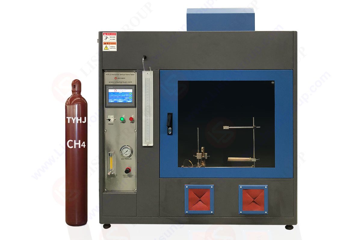
This HVR-LS Horizontal Vertical Flame Test Chamber meets the requirements of ANSI/UL94, IEC60695-11-3, IEC60695-11-4, IEC60695-11-10, IEC695-2-2 , GB- 4943, GB/T5169.15, GB/T5169.16, GB/T5169.17, GBT5169.22 Standard. Horizontal Vertical Flame Test Chamber uses a bunsenburner with a specified size and a specific gas source (methane or natural gas). According to a certain flame height and a certain flame angle, the test sample in a horizontal or vertical state is regularly burned. Secondly, the flammability is evaluated by the duration of the ignition and hot burning of the sample and whether the ignitor under the sample is ignited.

HVR-LS Horizontal Vertical Flame Tester
The flammability of HB&V (50W) and 5V (500W) materials is graded and evaluated. The horizontal and vertical combustion tester can provide fire protection enclosures for mobile equipment with a total mass exceeding 18kg and not exceeding 18kg. The material used for the fire protection enclosure of the standing equipment to be placed in the fire enclosure. The flammability of V-0, V-1, V-2, HB, 5V, HF-1, HF-2, HBF grade materials or foam plastics shall be graded and assessed.
It is suitable for the research of electrical and electronic products and their components such as lighting equipment, low-voltage electrical appliances, household appliances, machine tool electrical appliances, motors, power tools, electronic instruments, electrical meters, information technology equipment, electrical business equipment, electrical connectors and accessories, etc. production and quality inspection departments, also suitable for insulation materials, engineering plastics or other solid combustible materials.
Test method for the Horizontal Vertical Flame Tester procedure:
1. Prepare the wire, 25mm±1mm and 100mm±1mm away from the ignition end respectively. Six specimens and three specimens are measured, each specimen is marked with two marks perpendicular to the longitudinal axis of the spline.

Test Method for the Horizontal Vertical Flame Tester
2. Clamp the specimen at the far end of the 25mm marking line so that the longitudinal axis is approximately horizontal and the horizontal axis forms an angle of 45º±2º with the horizontal plane. Clamp a piece of horizontal wire mesh under the specimen. The distance between the lower bottom edge and the wire mesh is 10mm±1mm, and the free end of the sample is aligned with the free end of the wire mesh.
3. If the free end of the sample cannot be bent and the distance of 10mm±1mm specified in step 2 cannot be maintained, the support frame shown in the figure below should be used. With a distance of 10±1mm, the part of the support frame protruding from the free end of the sample is approximately 10mm. Sufficient clearance should be provided at the clamping end of the sample so that the support frame can move freely in the lateral direction.

Test Method for the Horizontal Vertical Flame Tester
4. Make the center axis of the blowtorch vertical, place the blowtorch far away from the sample, and adjust the blowtorch to make the blowtorch reach a stable state. When there is a dispute, use the A test flame as a reference.
5. Keep the central axis of the torch tube at an angle of approximately 45° to the horizontal plane while obliquely to the free end of the sample, and add the flame to the bottom edge of the free end of the sample. At this time, the central axis of the torch tube is at the same longitudinal bottom edge of the sample. As shown in the figure below on the vertical plane, the position of the torch should allow the flame to penetrate into the free end of the sample approximately 6mm in length.

Test Method for the Horizontal Vertical Flame Tester
6. As the front of the flame progresses along the specimen, withdraw the support at approximately the same rate to prevent the front of the flame from contacting the support frame, so as not to affect the flame or the combustion of the specimen.
7. Do not change the position of the flame and apply the flame for 30s±1s. If the front of the flame on the sample reaches 25mm below 30s, immediately remove the flame. When the flame front reaches the 25mm mark, restart the timer.
8. After the test flame is removed, if the sample continues to burn, record the elapsed time in seconds. When the front end of the flame passes the 100mm marking line, the damage length L shall be recorded as 75mm. If the flame front reaches the 25mm mark but fails to pass the 100mm mark, record the elapsed time t in seconds, and record the damage length L between the 25mm mark and the mark before the flame stops.
9. Test two more samples.
10. If only one sample in the third sample in the group does not meet the criterion of HB grade material in the standard, three samples in the other group should be used in the sample. All samples of the second group shall meet the criteria of the relevant level.
Classification: According to the record of the behavioral test data of the sample, the material should be classified into HB, HB40 and HB75 (HB=horizontal combustion).
Test method B Vertical combustion test procedure:
1. Clamp the upper end of the sample to a length of 6mm, with the vertical axis vertical, so that the lower end of the sample is 300mm±10mm higher than the horizontal cotton layer. The thickness of the cotton layer is not compacted. Its size is approximately 50mmx50mmx6mm, and its weight is 0.08g.
2. The longitudinal axis of the torch tube is in a vertical state, put the torch far away from the sample, and adjust the torch to produce a 50W flame test in accordance with the IEC60695-11-4-2011 standard, and wait for 5 minutes to make the torch A stable state is reached.
3. Keep the central axis of the torch tube vertical, add the flame center to the midpoint of the bottom edge of the sample, and at the same time make the top of the torch 10mm±1mm lower than this point, keep it for 10s±0.5s. According to the length and position of the sample change, move the blowtorch in the vertical plane if necessary.
4. When the sample after flame is extinguished, immediately re-place the test flame under the sample, keep the central axis of the torch tube in a vertical position, and keep the top of the torch at a distance of 10mm±1mm below the lower end of the sample for 10s ±0.5s, if necessary, as described in 9.2.3 of the standard, remove the torch to remove drippings. After the second flame is applied to the sample for 10s±0.5s, immediately turn off the torch or move it far enough away from the sample so that it does not affect the sample. At the same time, use the timing device to start measuring the afterflame time t2 and t2 of the sample. Afterglow time t3, accurate to the second.
5. Record t2, t3, and t2+t3. Also note whether any particles fall from the specimen and whether the cotton pad is ignited.
6. Repeat the fourth step until the sample is tested according to the 5 samples adjusted in the state of 9.1.1 in the standard and the sample adjusted in the state of 9.1.2.
7. If a group of five specimens processed under given conditions, only one specimen does not meet all the criteria of a certain classification, a group of five specimens subjected to the same conditioning shall be tested. As the total number of seconds of afterflame time tf, for V-0 class, if the total afterflame time is 51s~55s or for V-1 and V-2 class 21s~25s, a set of 5 samples should be added during the test, all samples of the second group shall meet all the criteria specified in the class.
Classification: According to the calculation of sample behavior and test record data, materials can be divided into V-0, V-1 and V-2.
Note: Before each horizontal burning test of the sample, the remaining residues on the wire mesh should be removed or replaced with a new wire mesh.
Lisun Instruments Limited was found by LISUN GROUP in 2003. LISUN quality system has been strictly certified by ISO9001:2015. As a CIE Membership, LISUN products are designed based on CIE, IEC and other international or national standards. All products passed CE certificate and authenticated by the third party lab.
Our main products are Goniophotometer, Integrating Sphere, Spectroradiometer, Surge Generator, ESD Simulator, EMI Receiver, EMC Test Equipment, Electrical Safety Tester, Environmental Chamber, Temperature Chamber, Climate Chamber, Thermal Chamber, Salt Spray Test, Dust Test Chamber, Waterproof Test, RoHS Test (EDXRF), Glow Wire Test and Needle Flame Test.
Please feel free to contact us if you need any support.
Tech Dep: Service@Lisungroup.com, Cell/WhatsApp:+8615317907381
Sales Dep: Sales@Lisungroup.com, Cell/WhatsApp:+8618917996096
Tags:HVR-LS

LISUN’s electric toy testing solutions cover IEC 62115, EN 71-1, ASTM F963 standards. Including electrical, mechanical, flammability tests to ensure toy safety compliance globally.

LISUN’s energy meter testing solutions align with IEC 62052-11, IEC 62053 series standards. Covering safety, electrical, environmental, and EMC tests, we help manufacturers meet global compliance...

LISUN’s audio-video communication testing solutions meet CISPR 13, IEC 60065, FCC Part 15 & EN 55032. Cover EMC, safety & performance tests for reliable AV equipment...

LISUN’s household and appliance switch testing solutions meet IEC 60669, IEC 61058, IEC 62271 standards. Covering electrical, mechanical & EMC tests for global compliance.
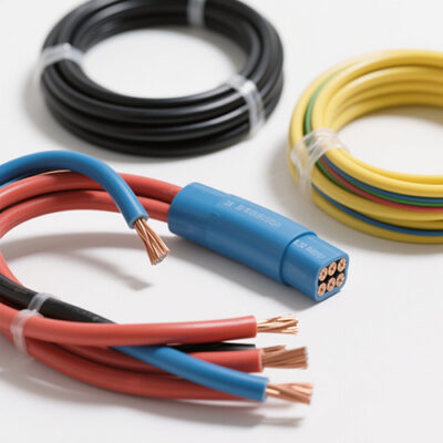
LISUN’s cable and wire test solutions meet IEC 60245-1, IEC 60227-1, IEC 60502-1 and IEC 60189 standards, covering electrical, mechanical, and safety tests for global compliance.

 中文简体
中文简体