LM-79 Moving Detector Goniophotometer (Mirror Type C)
LSG-6000

High Precision Rotation Luminaire Goniophotometer
LSG-1890B

High Precision Rotation Luminaire Goniospectroradiometer
LSG-1890BCCD

Goniophotometer for Automotive and Signal Lamps
LSG-1950

Goniophotometer for Traffic Signal Lamps
LSG-1950S

Compact Goniophotometer
LSG-1200A

Near Field Moving Detector Goniophotometer
LSG-1900B
Select an organization
to browse standards
Surge tests are considered critical because they are known best for finding turn-to-turn insulation weaknesses. These weaknesses begin at voltages above the operating voltage of the motor. They are the main causes of serious failures and the shutdown of a motor. Surge tests are also used for finding the hard shorts and several other mistakes in windings and coils.
They are also known as the ‘’surge comparison test’’ because the result obtained from one coil or phase is compared with another coil or phase. The reason for this act is that the coils are almost identical, so the results obtained are also identical to some extent. If the coils are not identical, the test is called the ‘’pulse-to-pulse test’’.

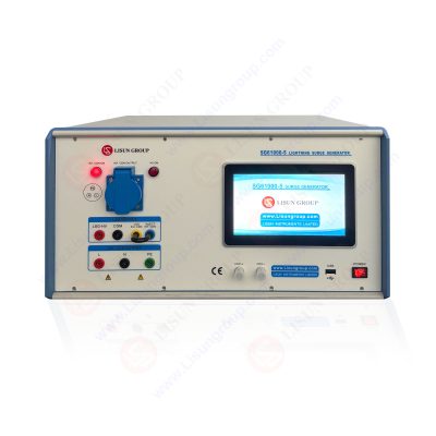
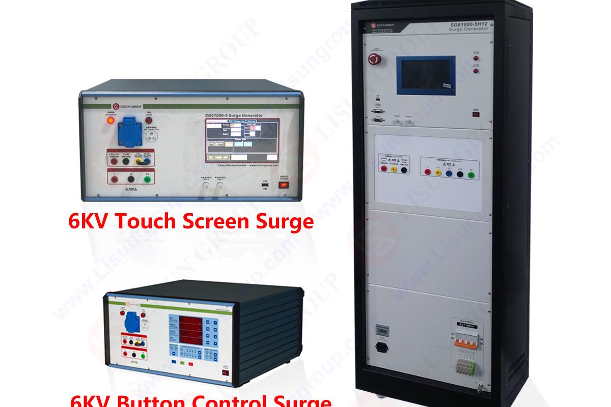
SG61000-5_Surge Generator
The surge test can detect some known failures in the underground cables. Some of them are listed below
• Turn-to-turn weaknesses and shorts
• Coil-to-coil weaknesses and shorts
• Phase-to-phase weaknesses and shorts
• Wrong turn current
• Wrong coil or group connections
• Short to ground
• High partial discharge
• Weaknesses to ground
• Partial blowout of random wound coils
A surge Generator is considered the backbone of an underground cable fault locator test system. It is used with a Pre-locator for the measurement of fault distance. It is also used with a Pin Pointer to find the fault spot’s location.
LISUN stocks the surge generators for multiple tests like immunity and surge tests and conducts compliance immunity tests. These surge generators mostly include a network of coupling and decoupling. This network can apply the power to the device under test for up to 16 AMPs.

• Connect the braided ground cable to a known earth ground point. Connect the test leads to the motor’s stator and ground lead to a paint-free point on the frame of the motor.
• Connect it now if you have the optional footswitch accessory—power on the power pack and the DX.
• Verify that the voltage control knob is zero as a safety feature.
• The test leads are connected to the high voltage power supply, the warning lamps on the power pack will light up, and the words lead energized will appear on the DX’s screen.
• If, for any reason, you need to disconnect the power to the test leads quickly, press the equipment stop button.
• This can be reset by turning it. Let’s start with the DC high pot testing.
• On the main screen of the DX, select the DC test. Select the power pack configuration.
• Select either thermoplastic or thermosetting corresponding to the type of insulation being tested. Enter the stator winding temperature.
• Turn the test selector switch to the high pot. It is important to note that only the lead 1 will be energized during the high pot test.
• Turn the power pack function switch to the 100 microamps per division position.
• If you have one, press and hold the push to test button or press and hold the footswitch.
• Smoothly, turn the voltage control knob to raise the voltage to your first step.
• In this case, it is 10,000 volts. Press the step button to initiate the step timer, which will be one minute long by default. On the other hand, the voltage is held at a constant value.
• The leakage current will diminish over time if the current value falls below half of the lowest division.
• Turn the power pack function knob to 10 microamps per division. The leakage current will continue to diminish if it again falls below half of the lowest division. Turn the Power Packs
• Function to 1 microamp or division.
• Watch the seconds remaining countdown.
• Return the Power Packs Function knob to 100 microamps per division when the step timer is complete. This will avoid an overcurrent trip.
• When you increase the voltage, turn the voltage control knob smoothly to increase the voltage to the next desired level.
• Adjust the current scale with the function knob as before. Continue this procedure for all steps.
• However, press the DC high pot instead of stepping again when you reach the final test voltage.
• This test will last for one minute by default.
• When the high pot test is completed, release the push to test button or the footswitch.
Save all the data.
• Return the voltage knob to zero. Turn the test. Select the knob to the lead ground position that the X will remind you to do this.
• To ensure the test circuit is adequately discharged, maintain the ground connection after testing for the same duration as the high voltage was applied.

DC Hipot and surge testing
These are surge test waveforms that are created during the surge tests.
• Now, we will perform surge testing on a three-phase motor on the main screen of the DX. Select the surge test.
• Select the power pack and verify that the voltage control knob is zero. Press the Power Pack function switch to the surge test position.
• Turn the test, select the knob to lead 1 and check that lead 1 is highlighted yellow on the DX.
• Press and hold the push to the test button or footswitch.
• Slowly increase the voltage knob until the surge wave can be seen, and then adjust the horizontal scale so that the waveform is shown across most or all of the screen.
• Slowly and continuously raise the voltage to the desired test value. In this case, 14,000 volts.
• Turning the knob smoothly minimizes the effects of ramping on the pulse to pull the CER.
• Release the push to test button or footswitch. Select the lead on the power pack and press to on the DX.
• Turn the voltage control knob to zero. Press and hold the push to the test button or the footswitch.
• Slowly increase the voltage to the desired test value as before.
• Repeat the procedure for the lead 3.
• Save the data.
• Turn the voltage control knob to zero and the Power Packs test. Select the switch to the lead ground.
This phenomenon in which a generator surge is referred to as surging. Power surging caused by the generator is never considered a normal case. It is a sign that something somewhere within your generator is not performing its function effectively.
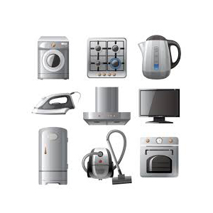
Yes, you can use a surge protector with your generator. Suppose you think that a surge caused by your generator can destroy your house’s appliances and electronic devices. In that case, the only solution to resolve this problem is to attach a surge protector.
Lisun Instruments Limited was found by LISUN GROUP in 2003. LISUN quality system has been strictly certified by ISO9001:2015. As a CIE Membership, LISUN products are designed based on CIE, IEC and other international or national standards. All products passed CE certificate and authenticated by the third party lab.
Our main products are Goniophotometer, Integrating Sphere, Spectroradiometer, Surge Generator, ESD Simulator Guns, EMI Receiver, EMC Test Equipment, Electrical Safety Tester, Environmental Chamber, Temperature Chamber, Climate Chamber, Thermal Chamber, Salt Spray Test, Dust Test Chamber, Waterproof Test, RoHS Test (EDXRF), Glow Wire Test and Needle Flame Test.
Please feel free to contact us if you need any support.
Tech Dep: Service@Lisungroup.com, Cell/WhatsApp:+8615317907381
Sales Dep: Sales@Lisungroup.com, Cell/WhatsApp:+8618117273997

LISUN’s Motor-Operated Tool | Power Tool Testing solutions strictly comply with a range of core international standards, providing full support for safety and electromagnetic compatibility (EMC)...

LISUN’s electric toy testing solutions cover IEC 62115, EN 71-1, ASTM F963 standards. Including electrical, mechanical, flammability tests to ensure toy safety compliance globally.

LISUN’s transformer test solutions meet IEC 61558-1, IEC 60076-1, IEC 62041 standards. Covering safety, performance, EMC tests, ensuring transformers comply with global requirements.

LISUN’s energy meter testing solutions align with IEC 62052-11, IEC 62053 series standards. Covering safety, electrical, environmental, and EMC tests, we help manufacturers meet global compliance...

LISUN’s household and appliance switch testing solutions meet IEC 60669, IEC 61058, IEC 62271 standards. Covering electrical, mechanical & EMC tests for global compliance.
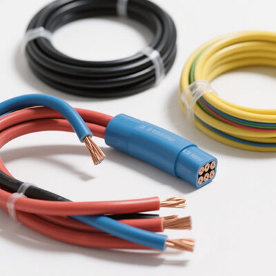
LISUN’s cable and wire test solutions meet IEC 60245-1, IEC 60227-1, IEC 60502-1 and IEC 60189 standards, covering electrical, mechanical, and safety tests for global compliance.
LISUN has all equipment according to the IEC60669 measurement, including environmental chamber, IP code waterproof dustproof test, switch lift test, etc.

Lisun can supply full test solutions for fluorescent lamp, including integrating sphere system, goniophotometer system, EMI EMC test, electronic ballast tester, electrical safety test, etc.

For the CFL design and manufactory, LISUN can supply a full quality control test solution, including photometric, colorimetric, electricity, flicker, IES candela distribution, surge test, electrical...

LISUN’s LED driver test solutions cover lab testing, online testing, EMC/EMI tests, and safety checks, meeting IEC 60335, UL 60335 standards for reliable performance evaluation.

 中文简体
中文简体