
LM-79 Moving Detector Goniophotometer (Mirror Type C)
LSG-6000

High Precision Rotation Luminaire Goniophotometer
LSG-1890B

High Precision Rotation Luminaire Goniospectroradiometer
LSG-1890BCCD

Goniophotometer for Automotive and Signal Lamps
LSG-1950

Goniophotometer for Traffic Signal Lamps
LSG-1950S

Compact Goniophotometer
LSG-1200A

Near Field Moving Detector Goniophotometer
LSG-1900B
Select an organization
to browse standards
Abstract
Conducted emissions, a critical component of electromagnetic interference (EMI), refer to the propagation of unwanted electromagnetic energy through conductive media such as power lines, cables, or connectors. Accurate measurement of conducted emissions is essential for ensuring electronic devices comply with international standards, avoiding interference with other equipment, and maintaining system reliability. This paper focuses on the principles, standards, and practical implementation of conducted emissions tests, with a detailed analysis of the LISUN EMI-9KB EMI Test Receiver system—a specialized tool designed for conducted and radiated emissions testing. The system’s configuration, technical specifications, compliance with international standards (e.g., CISPR15:2018, EN55015), and application scenarios are explored, highlighting its effectiveness in conducting precise and reliable conducted emissions tests.
1. Introduction
In an increasingly interconnected world, electronic devices coexist in dense electromagnetic environments, making electromagnetic compatibility (EMC) a paramount concern. EMI, which encompasses both conducted and radiated interference, can degrade device performance, cause malfunctions, or even lead to safety hazards. Among these, conducted emissions—electromagnetic disturbances transmitted via conductive paths—pose unique challenges due to their ability to spread through power grids and interconnecting cables, affecting multiple devices simultaneously.
Conducted emissions tests (CET) are designed to quantify these disturbances, ensuring devices meet regulatory limits. Compliance with CET standards is not only a legal requirement in most markets but also a mark of product quality. This paper examines the technical foundations of CET and demonstrates how the LISUN EMI-9KB Test Receiver system facilitates efficient and accurate testing, adhering to global standards.
Conducted emissions are unwanted electrical signals generated by an electronic device (Equipment Under Test, EUT) that propagate through power lines, signal cables, or other conductive pathways. Unlike radiated emissions, which travel through space, conducted emissions rely on physical connections, making them particularly impactful in shared power networks.
Key characteristics of conducted emissions include:
• Frequency range: Typically 9 kHz to 30 MHz for low-frequency conducted emissions, as defined by standards like CISPR16-1.
• Propagation paths: Power supply lines (common-mode and differential-mode interference) and signal cables.
• Measurement parameters: Voltage or current magnitude, often expressed in dBμV (decibels relative to 1 microvolt).
To ensure consistency in testing, several international standards govern conducted emissions measurements. The LISUN EMI-9KB system is designed to comply with the following critical standards:
| Standard | Title | Scope |
| CISPR15:2018 | Limits and methods of measurement of radio disturbance characteristics of electrical lighting and similar equipment | Specifies limits and test methods for conducted emissions from lighting equipment (e.g., LED drivers, fluorescent ballasts). |
| EN55015 | Limits and methods of measurement of radio disturbance characteristics of electrical lighting and similar equipment | European equivalent of CISPR15, harmonized for EU markets. |
| CISPR16-1 | Specification for radio disturbance and immunity measuring apparatus and methods – Part 1-1: Measuring apparatus | Defines technical requirements for EMI receivers and associated equipment used in conducted emissions tests. |
| EN55022 | Radio disturbance characteristics – Limits and methods of measurement | Applies to information technology equipment (ITE), specifying conducted emissions limits for devices like computers and servers. |

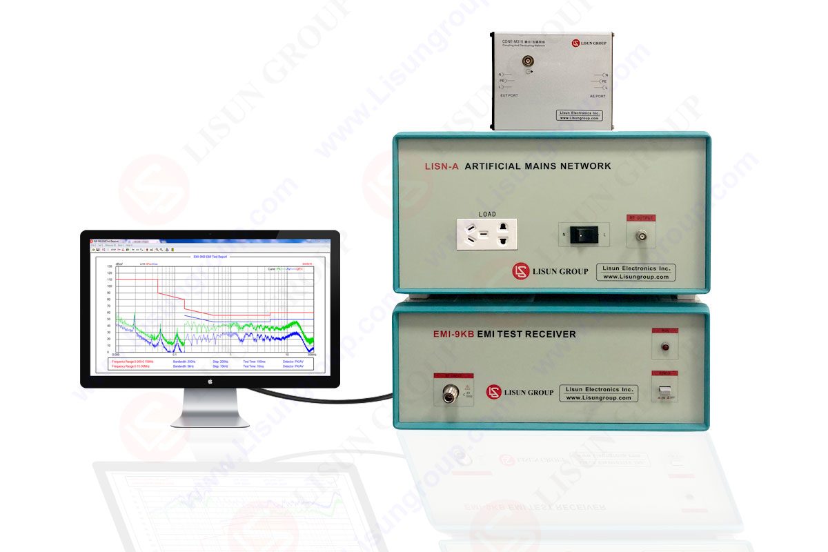
EMI-9KB EMI Test Receiver
The LISUN EMI-9KB is a dedicated system for conducted and radiated emissions testing, engineered to address the challenges of accurate EMI measurement. Its full-closure structure, constructed from high-conductivity materials, provides exceptional electromagnetic shielding, eliminating self-interference from the instrument itself—a critical factor in ensuring test accuracy.
The EMI-9KB system is modular, integrating essential components to perform comprehensive conducted emissions tests. Its core configuration includes:
EMI-9KB EMI Receiver: The central unit, covering a frequency range of 9 kHz to 300 MHz, equipped with detection modes (Peak (PK), Quasi-Peak (QP), and Average (AV))—the three primary methods specified by CISPR standards for measuring conducted emissions.
• LISN (Artificial Mains Network): A Line Impedance Stabilization Network that isolates the EUT from the mains power grid, providing a stable impedance (typically 50 Ω) for consistent voltage measurement of conducted emissions.
• CDNE-M316 Coupling/Decoupling Network: Required by the latest CISPR15:2018 standard (replacing older CDN devices), it couples conducted emissions from the EUT to the receiver while decoupling the mains power to prevent interference.
• Isolation Transformers: Prevent ground loops and reduce noise from the power supply, ensuring the EUT’s emissions are measured without external contamination.
• Attenuator: Protects the receiver from excessive signal levels, preventing damage and ensuring linear operation.
• Cables and Connectors: Shielded cables to minimize signal loss and external interference during transmission.
The performance of the EMI-9KB system is defined by rigorous technical parameters, ensuring compliance with CISPR16-1 and other standards. Key specifications are summarized in Table 2:
| Parameter | Specification (EMI-9KB) |
|---|---|
| Frequency Range | 9 kHz ~ 300 MHz |
| Frequency Stability | 1 × 10⁻⁶ |
| Frequency Resolution | 30 Hz (9 kHz ~ 150 kHz); 1 kHz (150 kHz ~ 30 MHz) |
| Test Tolerance | ±2 dB |
| Detection Modes | PK, QP, AV |
| Measurement Range | 20 dBμV ~ 140 dBμV |
| Scanning Step Frequency | 20 Hz ~ 2 MHz |
| Sweep Bandwidth | 200 Hz; 9 kHz; 120 kHz |
| PC Connectivity | USB; compatible with Windows 7/8/10/11 |
A typical conducted emissions test using the EMI-9KB system follows these steps:
EUT Preparation: The EUT (e.g., a LED driver) is placed on a non-conductive table, 80 cm above the ground, to simulate real-world installation.
System Connection:
• The EUT is connected to the LISN, which is linked to the mains power supply.
• The LISN’s measurement port is connected to the CDNE-M316, which then feeds the signal to the EMI-9KB receiver via the attenuator.
• Isolation transformers are inserted between the mains and LISN to eliminate ground loops.
Calibration: The system is calibrated using a reference signal generator to ensure measurement accuracy within the ±2 dB tolerance.
Software Configuration: The receiver is connected to a PC via USB, and LISUN’s proprietary software (compatible with Windows 7–11) is used to set parameters: frequency range (9 kHz ~ 30 MHz for conducted emissions), detection mode (QP for compliance testing per CISPR15), and sweep bandwidth (9 kHz for medium-wave interference).

Once configured, the test runs automatically, with the receiver scanning the frequency range and recording emission levels. The software generates a test report in international format, plotting emission levels (in dBμV) against frequency, overlaid with the relevant standard’s limit (e.g., 60 dBμV at 1 MHz for Class B devices under CISPR15).
For example, testing a LED driver might reveal emissions of 55 dBμV at 1 MHz (below the 60 dBμV limit), indicating compliance. If emissions exceed the limit (e.g., 65 dBμV at 5 MHz), the system can identify the frequency band, guiding engineers to add filters or shielded cables to mitigate the issue.
5. Advantages of EMI-9KB in Conducted Emissions Test
The EMI-9KB system offers several key advantages for conducted emissions testing:
• High Shielding Performance: Its full-closure, conductive structure eliminates self-EMI, ensuring measurements reflect only the EUT’s emissions.
• Compliance with Latest Standards: Integration of CDNE-M316 aligns with CISPR15:2018, avoiding obsolescence in global markets.
• Versatility: Compatible with optional components (e.g., shielding cabinets, pure power sources) allows adaptation to diverse testing environments.
• User-Friendly Operation: PC connectivity and intuitive software simplify parameter setup and data analysis, reducing test time.
6. Conclusion
Conducted emissions tests are indispensable for ensuring electronic devices coexist without interference, and compliance with international standards is a prerequisite for market access. The LISUN EMI-9KB Test Receiver system emerges as a robust solution for such tests, combining precise measurement capabilities, adherence to global standards (CISPR15:2018, EN55015, etc.), and user-friendly design.
By integrating critical components like LISN, CDNE-M316, and a high-performance receiver, the EMI-9KB system enables accurate quantification of conducted emissions, supporting manufacturers in validating product compliance and improving device reliability. As electromagnetic environments grow more complex, tools like the EMI-9KB will remain essential for maintaining EMC in modern electronics.
References
CISPR15:2018, Limits and methods of measurement of radio disturbance characteristics of electrical lighting and similar equipment.
CISPR16-1, Specification for radio disturbance and immunity measuring apparatus and methods – Part 1-1: Measuring apparatus.
LISUN GROUP, “EMI-9KB EMI Test Receiver,” https://www.lisungroup.com/products/emi-and-emc-test-system/emi-test-receiver.html (Accessed: August 2025).
EN55015, Limits and methods of measurement of radio disturbance characteristics of electrical lighting and similar equipment.

LISUN’s Motor-Operated Tool | Power Tool Testing solutions strictly comply with a range of core international standards, providing full support for safety and electromagnetic compatibility (EMC)...

LISUN’s transformer test solutions meet IEC 61558-1, IEC 60076-1, IEC 62041 standards. Covering safety, performance, EMC tests, ensuring transformers comply with global requirements.

LISUN’s household and appliance switch testing solutions meet IEC 60669, IEC 61058, IEC 62271 standards. Covering electrical, mechanical & EMC tests for global compliance.

For the CFL design and manufactory, LISUN can supply a full quality control test solution, including photometric, colorimetric, electricity, flicker, IES candela distribution, surge test, electrical...

 中文简体
中文简体