
LM-79 Moving Detector Goniophotometer (Mirror Type C)
LSG-6000

High Precision Rotation Luminaire Goniophotometer
LSG-1890B

High Precision Rotation Luminaire Goniospectroradiometer
LSG-1890BCCD

Goniophotometer for Automotive and Signal Lamps
LSG-1950

Goniophotometer for Traffic Signal Lamps
LSG-1950S

Compact Goniophotometer
LSG-1200A

Near Field Moving Detector Goniophotometer
LSG-1900B
Select an organization
to browse standards
Introduction:
The term “electromagnetic compatibility” (or “EMC”) refers to the ability of electrical equipment to function without causing interference to one another or to other systems. When evaluating the electromagnetic compatibility (EMC) of a device, EMI test receivers are important.
Physical testing with EMI test receivers is standard but may be time-consuming and expensive. The combination of EMI test receivers and modeling tools has emerged as a potent answer to these problems. This article will discuss how combining EMI test receivers with simulation tools may improve electromagnetic compatibility and how to go about doing so.
The Need for Simulation in EMI Design:
Product designs may be analyzed and optimized virtually with the use of simulation tools before being physically prototyped and tested. Simulations help engineers to anticipate and address possible EMI difficulties early in the design process by correctly simulating electromagnetic events and interactions. There are a number of benefits to using simulation tools in conjunction with EMI test receivers:
1. Early Design Assessment: Using simulation tools, engineers may do early analysis of a product’s electromagnetic compatibility (EMC) performance. This helps in the early discovery of electromagnetic interference (EMI) problems and the integration of design changes. Because of this early assessment, the number of time-consuming and resource-intensive design adjustments that are required will be cut down.
Design Optimization: By using simulation tools, one may be able to get a better understanding of the effect that a number of design choices have on the EMC characteristics of a product. Experimenting with alternate component placements, grounding techniques, and shielding configurations are some of the things that engineers could do in order to enhance EMC performance and decrease EMI dangers.
3. Cost Reduction: Using simulations to find and fix EMI problems may drastically cut down on the number of necessary physical prototypes for testing. Savings in raw materials, testing tools, and research space are all the direct results of this development.
Integration Methods:
Data and information are sent between the EMI test receiver and the simulation tool during integration. There are several approaches to integration:
1. Data Transfer: Electromagnetic interference (EMI) test receivers pick up authentic EMI waves in lab conditions. This information may be stored and then imported into modeling programs for verification and analysis. The captured EMI data is sent into the simulation program to model the product’s response to various environments.
2. Model-Based Integration: It is possible for EMI test receivers and simulation tools to use the same product models. Computer-aided design (CAD) software is often used to create these models, which accurately portray the product’s shape, materials, and electrical properties. By using the same models for both physical testing and simulation, EMI behavior may be accurately predicted.
3. Co-Simulation: In order to co-simulate, the EMI test receiver software and simulation program need to be operating in tandem, sharing data in real-time. In the process of doing physical testing, engineers may run virtual tests to compare and validate their findings in real time. Co-simulation allows designers to get a holistic view of the EMC performance of the product from the beginning to the end of the design process.
Benefits of Integration:
There are several advantages to optimizing product design using the combination of EMI test receivers and simulation tools:
1. Early EMI Risk Identification: Engineers may evaluate EMI dangers and EMC performance before building a physical prototype by using simulation tools. Engineers may save time and money in the long run by preventing unnecessary adjustments and rework to the product design by addressing these risks early on.
2. Design Iteration Optimization: By combining EMI test receivers with simulation software, engineers may run simulated tests and assess how various design decisions affect EMI performance. The time to market is cut down and the number of physical prototypes required is cut down via this iterative optimization approach.
3. Enhanced Design Understanding: Electromagnetic fields, currents, and voltages within the product may be seen and analyzed with the use of simulation software. Engineers may learn more about EMI and the elements that affect it. With this knowledge, designers may make better choices and implement more precise mitigation techniques.
4. Cost and Time Savings: Physical testing is time-consuming and costly; to save costs, EMI test receivers may be integrated with simulation tools. Engineers may save time, money, and resources on prototype development, test equipment, and lab time by diagnosing and fixing EMI problems digitally using simulations.

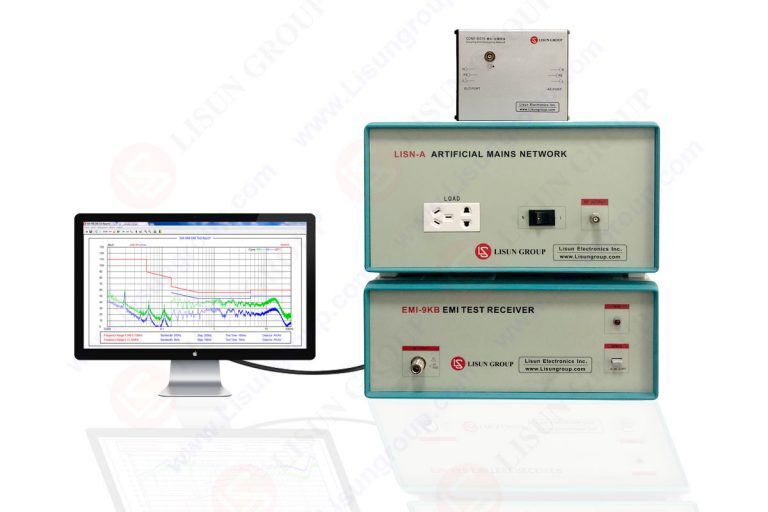
EMI-9KB EMI Test Receiver
Simulation Capabilities for EMI Analysis:
Simulation tools offer various capabilities that aid in EMI analysis and optimization:
1. Electromagnetic Field Simulation: In order to create a realistic model of the electromagnetic fields within and around the product, simulation tools use numerical approaches like the finite element method (FEM) and the finite-difference time-domain (FDTD). To better understand the flow of electromagnetic energy, locate possible coupling channels, and evaluate the efficacy of shielding, engineers may now view and analyze the data in three dimensions.
2. Signal Integrity Analysis: The effect of electromagnetic interference on the product’s signal integrity may be evaluated through EMI simulators. Engineers may assess the vulnerability of vital signals to EMI and maximize signal integrity via design changes if they take into account things like signal propagation, crosstalk, and ground bounce.
3. EMI Coupling Analysis: The simulation software may examine the methods of connectivity between the product’s various parts and subsystems. Engineers are able to take the necessary precautions against interference by using the results of this research to pinpoint the origins of the problem, whether it be radiated emissions, conducted emissions, or magnetic coupling.
4. Component Modeling and Simulation: Engineers may simulate the product’s individual parts using simulation software. This includes the product’s PCBs, connections, cables, and integrated circuits. Engineers may evaluate how these parts affect EMI performance by using precise models of their electrical behavior. You can get best EMI test receivers from LISUN.
Workflow for Integrated EMI Testing and Simulation:
Integrating EMI test receivers with simulation tools follows a systematic workflow:
1. Model Creation: Using computer-aided design (CAD) software, engineers create detailed virtual prototypes of the final product, down to the smallest geometric and material attributes and electrical functioning. Both simulations and experimental testing may be based on these models.
2. Physical Testing: In order to capture real-world EMI signals and performance data, EMI test receivers are utilized during physical testing of the device. The test findings are used to verify and calibrate future simulations.
3. Simulation Setup: The CAD models are used to populate the simulation tool with data before the engineers run the simulation. Materials and their electrical characteristics must be defined, signal routes must be integrated, and EMI sources and loads must be detailed.
4. Simulation Execution: The electromagnetic analysis is carried out by the simulation tool in accordance with the specified parameters. The simulated EMI behavior, including radiated and conducted emissions as well as interference situations, may be seen by engineers.
5. Data Comparison and Validation: Reference data from physical testing using EMI test receivers is compared with the findings from the EMI simulations. When there is a discrepancy between the simulated and measured data, we look into the cause and make iterative changes to the design until the two sets of data are consistent.
6. Design Optimization: Changes in component location, grounding schemes, shielding configurations, or filtering methods are implemented by engineers based on simulation findings to achieve optimal product design. EMC performance may be enhanced thanks to the simulation tool’s fast iterations and evaluation of design modifications.
7. Documentation and Reporting: Documentation for simulations, analyses, and design suggestions are all produced by the unified process. Use this record as a guide for meeting applicable laws and regulations.
Conclusion:
Optimizing a product’s electromagnetic compatibility may be achieved via the combination of EMI test receivers and simulation tools. Engineers may save time and money by reducing the number of design iterations required to address EMI concerns, as well as by better understanding EMI behavior via the use of simulation.
Engineers may make better design choices, deploy more focused mitigation techniques, and guarantee compliance with regulatory requirements when they combine physical testing with EMI test receivers and virtual simulations.
The integration of EMI test receivers with simulation tools is becoming more important for producing robust and EMC-compliant product designs as the complexity of electronic devices continues to increase.
Lisun Instruments Limited was found by LISUN GROUP in 2003. LISUN quality system has been strictly certified by ISO9001:2015. As a CIE Membership, LISUN products are designed based on CIE, IEC and other international or national standards. All products passed CE certificate and authenticated by the third party lab.
Our main products are Goniophotometer, Integrating Sphere, Spectroradiometer, Surge Generator, ESD Simulator Guns, EMI Receiver, EMC Test Equipment, Electrical Safety Tester, Environmental Chamber, Temperature Chamber, Climate Chamber, Thermal Chamber, Salt Spray Test, Dust Test Chamber, Waterproof Test, RoHS Test (EDXRF), Glow Wire Test and Needle Flame Test.
Please feel free to contact us if you need any support.
Tech Dep: Service@Lisungroup.com, Cell/WhatsApp:+8615317907381
Sales Dep: Sales@Lisungroup.com, Cell/WhatsApp:+8618117273997

LISUN’s Motor-Operated Tool | Power Tool Testing solutions strictly comply with a range of core international standards, providing full support for safety and electromagnetic compatibility (EMC)...

LISUN’s transformer test solutions meet IEC 61558-1, IEC 60076-1, IEC 62041 standards. Covering safety, performance, EMC tests, ensuring transformers comply with global requirements.

LISUN’s household and appliance switch testing solutions meet IEC 60669, IEC 61058, IEC 62271 standards. Covering electrical, mechanical & EMC tests for global compliance.

For the CFL design and manufactory, LISUN can supply a full quality control test solution, including photometric, colorimetric, electricity, flicker, IES candela distribution, surge test, electrical...

 中文简体
中文简体