LM-79 Moving Detector Goniophotometer (Mirror Type C)
LSG-6000

High Precision Rotation Luminaire Goniophotometer
LSG-1890B

High Precision Rotation Luminaire Goniospectroradiometer
LSG-1890BCCD

Goniophotometer for Automotive and Signal Lamps
LSG-1950

Goniophotometer for Traffic Signal Lamps
LSG-1950S

Compact Goniophotometer
LSG-1200A

Near Field Moving Detector Goniophotometer
LSG-1900B
Select an organization
to browse standards
I. The Functions of a High Precision Goniophotometer
High Precision Goniophotometer have the following functions: Testing the light intensity distribution curve, light intensity data, beam angle, total flux, lamp efficiency, regional flux, upward flux, downward flux, illuminance distribution, utilization factor, luminance limitation curve, glare grade, maximum allowable distance ratio, illuminance curve, effective average illuminance curve, spatial color distribution, average color parameters, etc. Then let’s take a look at the measurement environment conditions and photometric definitions for distributive photometry.

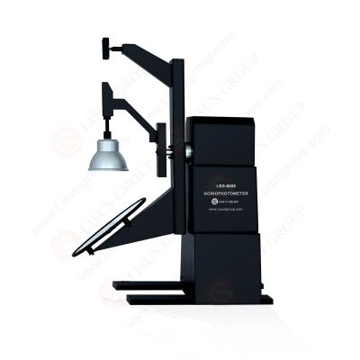
LM-79 Moving Detector Goniophotometer (Mirror Type C)
LISUN LSG-6000 Moving Detector Goniophotometer (Mirror Type C) was manufactured by LISUN completely meets LM-79-19, IES LM-80-08, COMMISSION DELEGATED REGULATION (EU) 2019/2015, CIE-121, CIE S025, SASO 2902, IS16106 and EN13032-1 clause 6.1.1.3 type 4 requirements. LSG-6000 is the latest upgraded product of LSG-5000 and LSG-3000 in compliance with the requirements of the LM-79-19 standard Clause 7.3.1, its an automatic light distribution intensity 3D curve testing system for measuring light. The darkroom can be designed according to the customer’s existing room size.
II. Parameters Measured by the High Precision Goniophotometer
The measured parameters include: light intensity distribution curve, light intensity data, effective luminescence angle, beam angle, total flux, regional flux, upward flux, downward flux, lamp efficiency, iso-illuminance map, iso-light intensity map, utilization factor, luminance limitation curve, glare grade, maximum allowed distance ratio, lamp probability curve, UGR unified glare value, effective average illuminance curve, etc.
III. Installation and Measurement of Luminaires by the High Precision Goniophotometer
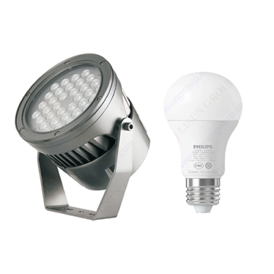
Select the luminaire (or light source) to be tested. The selected test luminaire (or light source) should meet the relevant national standards, be representative, and reflect the performance of the tested luminaire (or light source) type. For new light sources, the enterprise standards of the product should be complied with, and aging treatment should be carried out before testing. When installing the tested luminaire (or light source), wear clean gloves, wipe off dirt spots on the surface of the luminaire (or light source) before testing, and when installing the luminaire (or light source) in the test system, pay attention to aligning the center of the luminaire’s emitting surface (or the center of the light source emission) with the center of the “+” character, and record the angular scale value of the turntable. Clamp the wires at both ends of the tested luminaire (or light source). Note that the two pins of one clamp are plugged into the red and blue sockets, and the two pins of the other clamp are plugged into the yellow and green sockets, and then start zero-point measurement. After the zero-point test is completed, the result will be automatically stored in the system file. If the power of the tested luminaire (or light source) is not more than 1KW, turn the boat switch on the cabinet panel to the “CF” position, adjust the output switch of the frequency converter until the voltage data displayed on the electric meter is the rated voltage corresponding to the luminaire (or light source), and then turn on the tested luminaire (or light source ) and wait for it to emit light stably. Generally, the thermal radiation source needs 15 minutes, and the gas discharge source needs 30 minutes. If the power of the tested luminaire (or light source) is more than 1KW, turn the boat switch on the cabinet panel to the “OUTER” position, power the tested luminaire (or light source) directly from the purifying power supply and voltage regulator, turn on the tested luminaire (or light source) and wait for it stable. Generally, the thermal radiation source needs 15 minutes, and the gas discharge source needs 30 minutes.
IV. Environment Conditions of the High Precision Goniophotometer
1. Air temperature: 25℃ ± 1℃;
2. Thermal environment: The installation method is the main path of device heat dissipation, which may greatly affect the measurement results. The tested SSL products should be installed on the measuring instrument so that cooling effect can be slightly achieved through the heat conduction of the matching facilities.
3. Airflow: The airflow on the surface of the tested SSL product may greatly change the electrical value and luminal value. The airflow around the tested SSL product should make the normal convective gas unaffected. It is obviously not advisable that some domestic equipment manufacturers adopt the method of inputting cold air into the integrating sphere in order to ensure that the air temperature meets the requirements. As for how to ensure the air temperature as much as possible during the test, there are some small skills in the test process, which will be mentioned in the next few blog posts. In addition, some distributive photometers use light rotating structure with too high speed, which obviously also violates this principle.
V. Preparation before Operation

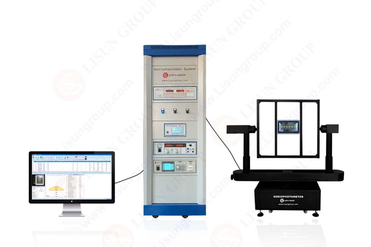
1. Before operation, the test personnel need to check the signal lines, control lines and power lines between each part of the LSG-6000 distributive photometer system to see if they are properly connected.
2. Turn the key switch on the cabinet panel of the system to turn on the main power supply, then press the “Motor” button to turn on the power supply of the mechanical part, press the “Meter” button to turn on the photometric tester and angle measuring controller in the cabinet, and then press the LS2010 electric meter switch to turn on the electric meter power supply.
3. Observe whether the test instruments and mechanical parts are online normally. Under normal circumstances, all the instruments except the reference signal will show “0” immediately, if it shows “0”, it indicates that the test instruments are not connected to the mechanical parts normally, turn off the power supply of the instruments in the cabinet and turn it on again.
4. Turn the boat switch on the cabinet panel to “CF”.
5. Turn on the computer system power supply, wait for the computer to enter the Windows interface, double LSG-6000 system.
Lisun Instruments Limited was found by LISUN GROUP in 2003. LISUN quality system has been strictly certified by ISO9001:2015. As a CIE Membership, LISUN products are designed based on CIE, IEC and other international or national standards. All products passed CE certificate and authenticated by the third party lab.
Our main products are Goniophotometer, Integrating Sphere, Spectroradiometer, Surge Generator, ESD Simulator Guns, EMI Receiver, EMC Test Equipment, Electrical Safety Tester, Environmental Chamber, Temperature Chamber, Climate Chamber, Thermal Chamber, Salt Spray Test, Dust Test Chamber, Waterproof Test, RoHS Test (EDXRF), Glow Wire Test and Needle Flame Test.
Please feel free to contact us if you need any support.
Tech Dep: Service@Lisungroup.com, Cell/WhatsApp:+8615317907381
Sales Dep: Sales@Lisungroup.com, Cell/WhatsApp:+8618117273997
LISUN’s indoor and outdoor LED test solutions meet IEC 60598-1, IEC 62722-2-1, CIE 121 standards, covering safety, photometry, and environmental tests for global compliance.

 中文简体
中文简体