
LM-79 Moving Detector Goniophotometer (Mirror Type C)
LSG-6000

High Precision Rotation Luminaire Goniophotometer
LSG-1890B

High Precision Rotation Luminaire Goniospectroradiometer
LSG-1890BCCD

Goniophotometer for Automotive and Signal Lamps
LSG-1950

Goniophotometer for Traffic Signal Lamps
LSG-1950S

Compact Goniophotometer
LSG-1200A

Near Field Moving Detector Goniophotometer
LSG-1900B
Select an organization
to browse standards
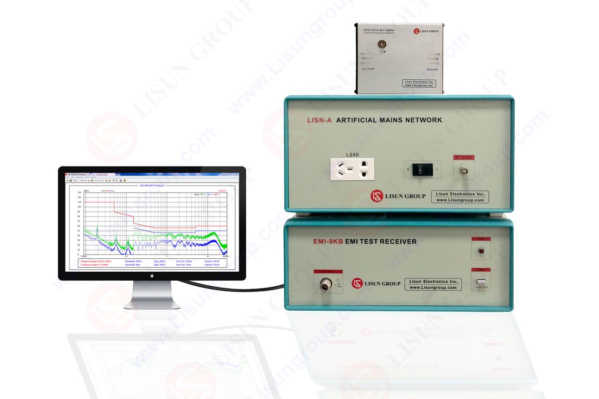
The EMI-9KB is an automatic EMI receiver system for radiation conduction or conducted emissions testing. THE FOLLOWING CLOSURE STRUCTURE PRODUCES the EMI-9KB receiver and a strong material (electro-conductible). This strong electro-conductible material has a high shielding effect.
Due to advanced technology for the EMI testing system, EMI test receiver has resolved the issue of the instrument self-EMI problem. The results of the tests are as per the international format of the test report. Interestingly, the EMI test system EMI-9KB fully meets CISPR15:2018, CISPR16-1, GB17743, FCC, EN55015 and EN55022.
The whole system contains four boxes. One box is the EMI receiver, the second is the LISN artificial network, the third is CDNE Coupling/ Decoupling Network, and the last contains three isolation transformers. Other accessories include two coaxial cables, attenuators, RS232 communication cable, RS232-USB converter, sample connection wires.

EMI-9KB_EMI Receiver System
A plastic bag is in the package that contains a CD, calibrate certificates, and guarantee cards. There is a software user manual, operation video, and related standards in the CD.
• Frequency range for detection: 9kHz~1GHz (EMI-9KC), 9kHz~300MHz (EMI-9KB), 9kHz~30MHz (EMI-9KA)
• Stability of Frequency: 1×10^-6
• Resolution of Frequency: (9kHz~150kHz) 30Hz; (150kHz~30MHz) 1kHz
• Test Tolerance: ±2 dB
• Method for Measurement and Detection: PK, QP, and AV
• Frequency scanning step length: 20Hz~2MHz
• Sweep bandwidth: 200Hz; 9kHz; 120kHz
• Connect the PC via USB cable and software. It can run on Win7, Win8 and Win10, Win11
Connect the EMI test receiver to the computer via RS232 cable or RS232-USB converter. Connect the power cord to one of the small isolation transformers. Only one of the LISN artificial networks and CDNE coupling/ decoupling network need to be connected in one test. Connect the power cord of the LISN artificial network to the big isolation transformer. Connect the sample to ‘LOAD’.
This is the L/N line switch. Use the attenuator and coaxial cable to connect the LISN artificial network to the EMI receiver. Conducted interference of some samples may be relatively high. The attenuator is used to protect the EMI receiver. Connect the ‘AE’ port to the big isolation transformer. Connect the sample to the EUT port.
Use coaxial cables to connect the CDNE coupling/ decoupling network to the EMI receiver. There is no need to connect the attenuator for CDNE. It is important to note here that the big transformer supplies power to the sample via LISN or CDNE. So, please equip with the appropriate power sources according to your samples.
• Power source
• The big isolation transformer
• LISN/ CDNE
• The sample
• Connect the power cords of the computer and its monitor to the other small isolation transformer.
• Copy all the files in the CD to the computer and install the software. The EMI receiver can be connected to the computer using the RS232 cable or RS232-USB converter.
• The driver of the converter is in the small CD, and the small CD is in the box of the converter.
• Confirm the COM port in the ‘Device Manager’ of the computer. Double click to open the software.
• Click ‘OK’ to enter the main interface of the software. Manually select the correct communication port.
• The unclickable grey buttons on the software navigation will become clickable if the communication between the computer and the EMI test receiver is good. Select or add the test standards.
•’Scan Parameter’ : normally just use the default settings.
• Select or add the correct attenuator being used. Select the curves to be displayed.
• The standard lines displayed on the software interface are QP and AV limit lines.
• Click ‘SCAN’ to start the test.
• The actual curves tested are PK and AV curves. After the scan is over, the software will prompt a message.
• The sample meets the standard if the measured AV line is lower than the AV limit line and the measured PK line is lower than the QP limit line.
• If the PK line is higher than the QP line in some frequency ranges, we need to do a final test to confirm that the sample meets the standard or not.
• Click ‘Final Measure’. Automatically, test at most 20 points QP value. The red X points are the final QP value.
• The sample would meet the standard if the QP measured values were lower than the OP limit curve.
• After scanning and final tests are finished, you can click to print the test report.
The red data in the table is the point where the QP value exceeds the limit curve in the final test. There may be a high peak pulse when the sample is installed, turned on, turned off, and disassembled. It may damage the device. The operation stops before the test must be in the following order.
Now, connect the coaxial cable to the EMI test receiver. Connect and power on the sample. Connect the coaxial cable to the LISN or CDNE. The operation steps after the test must be in the following order: disconnect the coaxial cable from LISN or CDNE, disconnect the sample.
If you want to turn on the system during the test, click the software ‘STOP’ to stop the test.
Electromagnetic Disturbance reduces the performance of an electrical equipment or an electronic device. It works abnormally or usually fails. The test can be divided into a conducted interference test and a radiated interference test. LISUN EMI-9KB is considered an automatic EMI test receiver system for Electromagnetic Interference Radiation Conducted emission testing. EMI test receiver can do both the conducted interference test and radiated interference test.
An EMI test receiver is an electronic noise that interferes with the cable signals and reduces the signal integrity. Electromagnetic radiation sources usually generate this receiver.

Lisun Instruments Limited was found by LISUN GROUP in 2003. LISUN quality system has been strictly certified by ISO9001:2015. As a CIE Membership, LISUN products are designed based on CIE, IEC and other international or national standards. All products passed CE certificate and authenticated by the third party lab.
Our main products are Goniophotometer, Integrating Sphere, Spectroradiometer, Surge Generator, ESD Simulator Guns, EMI Receiver, EMC Test Equipment, Electrical Safety Tester, Environmental Chamber, Temperature Chamber, Climate Chamber, Thermal Chamber, Salt Spray Test, Dust Test Chamber, Waterproof Test, RoHS Test (EDXRF), Glow Wire Test and Needle Flame Test.
Please feel free to contact us if you need any support.
Tech Dep: Service@Lisungroup.com, Cell/WhatsApp:+8615317907381
Sales Dep: Sales@Lisungroup.com, Cell/WhatsApp:+8618117273997

LISUN’s Motor-Operated Tool | Power Tool Testing solutions strictly comply with a range of core international standards, providing full support for safety and electromagnetic compatibility (EMC)...

LISUN’s transformer test solutions meet IEC 61558-1, IEC 60076-1, IEC 62041 standards. Covering safety, performance, EMC tests, ensuring transformers comply with global requirements.

LISUN’s household and appliance switch testing solutions meet IEC 60669, IEC 61058, IEC 62271 standards. Covering electrical, mechanical & EMC tests for global compliance.

For the CFL design and manufactory, LISUN can supply a full quality control test solution, including photometric, colorimetric, electricity, flicker, IES candela distribution, surge test, electrical...

 中文简体
中文简体