LM-79 Moving Detector Goniophotometer (Mirror Type C)
LSG-6000

High Precision Rotation Luminaire Goniophotometer
LSG-1890B

High Precision Rotation Luminaire Goniospectroradiometer
LSG-1890BCCD

Goniophotometer for Automotive and Signal Lamps
LSG-1950

Goniophotometer for Traffic Signal Lamps
LSG-1950S

Compact Goniophotometer
LSG-1200A

Near Field Moving Detector Goniophotometer
LSG-1900B
Select an organization
to browse standards
Abstract
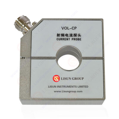
What does an RF current probe measure? This is a fundamental question concerning a core technique in Electromagnetic Compatibility (EMC) testing. An RF current probe is a non-contact sensor specifically designed to measure radio-frequency interference currents, particularly common-mode interference currents, flowing in wires or cables, typically within the frequency range of 9 kHz to 300 MHz or higher. It plays an irreplaceable role in evaluating the conducted disturbance emissions of electrical and electronic equipment and troubleshooting electromagnetic interference (EMI) issues. This article aims to provide a systematic explanation of the working principle, core performance parameters of RF current probes, and their application in mainstream EMC standards (such as CISPR 15, GB/T 17743). It will conduct an in-depth analysis of its transfer admittance characteristics and, using the LISUN VOL-CP RF Current Probe as an example, explain how to utilize this equipment to accurately measure the disturbance voltage on wired network ports of products like lighting equipment, offering key technical guidance for product EMC design and compliance testing.
Introduction
In the field of electromagnetic compatibility testing, engineers commonly use spectrum analyzers or receivers to measure the radiated emissions or the disturbance voltage conducted via the power lines of equipment. However, how can the RF interference energy generated by other wired interfaces (such as data lines, control lines, communication lines) besides the power port be quantified? What does an RF current probe measure? The answer is precisely these undesirable RF interference currents on cables that may cause performance degradation in surrounding equipment. Unlike voltage probes that require breaking the circuit, the clamp-on, non-invasive design of an RF current probe allows it to be clamped directly onto the cable under test without affecting the normal operation of the circuit under test. It converts the high-frequency current signal in the wire into a voltage signal proportionally for analysis by the receiving equipment. Understanding its measurement target and principle is the foundation for accurate EMC diagnosis and compliance verification. This article will analyze the core functions of the RF current probe and demonstrate its application in standard testing.
1. Measurement Target and Working Principle of the RF Current Probe
1.1 Core Measurement Target: Common-Mode Interference Current
The RF current probe primarily measures the common-mode current on a conductor. In the context of EMC, interference currents are divided into differential-mode and common-mode currents:
The RF current probe has very low coupling efficiency for differential-mode currents but is highly sensitive to common-mode currents. Therefore, it essentially measures the potential of a cable to radiate or receive electromagnetic energy as an antenna, i.e., it measures the unintended common-mode interference current on the cable.
1.2 Working Principle: A Current-to-Voltage Transformer
An RF current probe is essentially a broadband current-to-voltage transformer. Its core is a toroidal magnetic core (usually made of ferrite material) around which a coil is wound. When the conductor under test passes through the central aperture of the probe, the RF current in the conductor generates an alternating magnetic field around it. This magnetic field induces a corresponding magnetic flux in the probe’s toroidal core, which in turn generates an induced voltage across the probe’s coil. This induced voltage (V_out) is proportional to the current in the conductor (I_in), with the proportionality constant being the probe’s transfer impedance (Z_t) or transfer admittance (Y_t).
The relationship is: V_out = Z_t * I_in. In engineering, its logarithmic form, the transfer admittance (unit: dB S), is more commonly used. It intuitively reflects the probe’s sensitivity at different frequencies.
2. Interpretation of Core Performance Indicators: Focusing on Frequency Response Characteristics
A typical Frequency vs. Transfer Admittance Characteristic Curve is key to understanding probe performance. Taking the provided curve as an example, it reveals the response characteristics of the VOL-CP probe across different frequency bands:
3. Standard Application Scenario: Disturbance Voltage Testing on Wired Ports of Lighting Equipment
The second system block diagram clearly illustrates a typical application of the RF current probe in standard testing. Taking EMC testing of lighting equipment (e.g., LED drivers) as an example, according to standards like CISPR 15 / GB/T 17743:
This method avoids the circuit loading effects of directly connecting a voltage probe in parallel, enabling accurate and repeatable measurement of conducted disturbances from non-power ports.
4. Key Performance Parameters and Selection Points
When selecting a qualified RF current probe, it is crucial to focus on the following performance parameters, which collectively determine measurement accuracy and reliability.
Table 1: Key Performance Parameters and Significance of RF Current Probes (Using VOL-CP as an Example)
| Parameter Item | Technical Specification (VOL-CP Example) | Parameter Significance & Selection Consideration |
|---|---|---|
| Usable Frequency Range | 20 Hz – 300 MHz | Defines the total frequency span over which the probe can operate. Must cover the frequency bands required by the target test standard (e.g., CISPR 15 requires 9 kHz – 30 MHz). |
| Flat Region Range (-3dB) | 0.15 MHz – 160 MHz | Core indicator. The probe’s sensitivity is stable in the flat region, ensuring the most reliable measurement results. Ensure the primary disturbance frequencies of the EUT fall within this interval. |
| Transfer Admittance (Flat Region) | Approx. -15.4 dB S | Represents the probe’s sensitivity. This value must be stable and known for accurately converting receiver readings to current values. |
| Insertion Impedance | ≤ 0.8 Ω | The additional impedance introduced into the original circuit when the probe is clamped onto the conductor. A lower value means less disturbance to the circuit under test. |
| Maximum Current Rating | 100A (<400Hz), 2A (RF CW) | Specifies the maximum continuous current (power frequency/RF) the probe can safely handle, preventing core saturation or damage. |
| Voltage Standing Wave Ratio (VSWR) | < 2 (f ≥ 10 MHz) | Reflects the matching degree between the probe’s output and the 50Ω transmission line (connected to the receiver). A lower VSWR means less signal reflection and more accurate high-frequency measurement. |
| External Magnetic Field Rejection | > 40 dB | Characterizes the probe’s ability to suppress interference from external spatial magnetic fields. High immunity ensures measurement targets only the current in the clamped conductor, even in complex electromagnetic environments. |
| Probe Aperture (Inner Diameter) | 22 mm | Determines the maximum cable diameter or harness size that can be accommodated. |
5.Conclusion
What does an RF current probe measure? It accurately measures the unintended radio-frequency common-mode interference currents on the cables of electronic equipment’s wired ports, which may cause electromagnetic compatibility issues. By converting the unmeasurable current into a measurable voltage, it becomes the only effective tool for performing disturbance voltage tests on wired ports as per standards like CISPR 15 and GB/T 17743. A high-performance probe like the LISUN VOL-CP, with its wide and flat frequency response, low insertion impedance, and high immunity to external magnetic fields, ensures the accuracy and repeatability of measurement data across a broad frequency band. For EMC engineers in fields such as lighting, household appliances, and IT equipment, a deep understanding of what an RF current probe measures and its performance parameters is not only essential for completing compliance tests but also a powerful tool for in-depth EMC problem diagnosis and design optimization. Correctly selecting and using such a probe means being able to more clearly “hear” the electromagnetic “noise” emitted by equipment cables, thereby laying a solid foundation for creating quieter, more compatible electronic products.
Tags:VOL-CP

 中文简体
中文简体