
LM-79 Moving Detector Goniophotometer (Mirror Type C)
LSG-6000

High Precision Rotation Luminaire Goniophotometer
LSG-1890B

High Precision Rotation Luminaire Goniospectroradiometer
LSG-1890BCCD

Goniophotometer for Automotive and Signal Lamps
LSG-1950

Goniophotometer for Traffic Signal Lamps
LSG-1950S

Compact Goniophotometer
LSG-1200A

Near Field Moving Detector Goniophotometer
LSG-1900B
Select an organization
to browse standards
I. The Structure and Basic Principle of Optical Integrated Sphere
The basic principle of an optical integrated sphere is to have a light source at the center of the sphere which emits light which is then diffused onto the coating on the inner walls of the sphere. The diffused light passes through diffusion and continues to cycle until the light flux is the same across the entire inner surface of the sphere. Then a detector mounted on the ball wall reads out the light flux emitted by the light source.
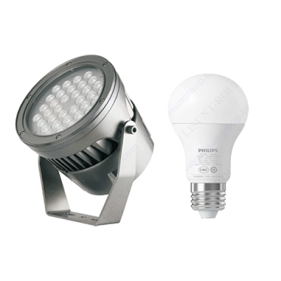
Generally, optical integrated spheres can only be used to test the color temperature, light flux, color coordinates, color rendering index, luminous efficiency and spectrum of light sources emitting omni-directional light. The color rendering index is the difference between the X and Y values calculated by the optical electric inspection system software and the standard light source. The smaller the number, the higher the accuracy. Luminous efficiency is the ratio of the total light flux emitted by the light source to the electrical power (watt) consumed by the light source, expressed in lm/w. For example, if the total light flux of lamps A and B are 100lm respectively and lamp A consumes 10W while lamp B consumes 20W, then it could be said that lamp A is more energy efficient than lamp B.

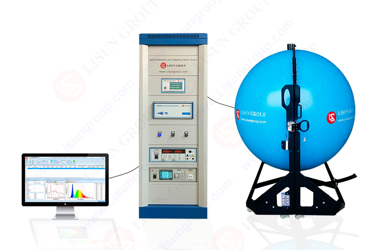
High Precision Spectroradiometer Integrating Sphere System LPCE 2(LMS-9000)
The latest laboratory integrated sphere is equipped with an optical probe. The probe can be used for measurement and sampling. There is a baffle painted with the same coating as the inner wall of the ball between the light source and the probe to prevent light from the source from shining directly to the probe. The integrated sphere in the laboratory is a hollow sphere composed of cast iron, the inside of which is coated with a white, rough coating, mainly composed of barium sulfate, which is mainly used to generate diffuse reflection to make the light intensity on the whole surface of the sphere consistent. There are holes on the ball wall for installing probes which are connected to an external high-precision and fast-acting spectral radiation meter.
The main diameters of the integrated sphere used in the laboratory are 0.3m, 0.5m, 1m, 1.5m, 1.75m and 2m. According to different lamps, different diameter integrating spheres should be selected for testing.
II. Measurement Method of Optical Integrating Sphere

1. Related Definition Background Signal:
It can be understood as some scattered signals output from the system without any signal input. For example, when the light source of the integrated sphere is not lit, the measured light flux should be 0, while some small signals can still be read out. This kind of signal can be considered as the background signal. Detection Limit: Refers to the minimum limit that can be measured by the device or method. In order to avoid the interference of the background signal, it is usually necessary to calibrate the zero first, that is, to filter out the background signal. In other words, all signals smaller than the background signal will be filtered out, and the background signal can be understood as the detection limit of this device. Standard Lamp: Various electric light sources used to replicate and maintain the unit and value transfer of luminance and radiance. They are standard measuring instruments in optical radiation measurement, that is, lamps calibrated to emit fixed light flux under calibration conditions (specific current or voltage).
2. Measurement Method
Optical Integrated Sphere adopts the method of relative comparison measurement, and the actual measurement value is calculated by comparing with the standard lamp, so it is usually necessary to calibrate with the standard lamp before measurement. Calibration means to use a standard lamp to let the device establish a standard for comparison with the actual measured value. In fact, the calibration of the device, the characteristics value obtained by using different standard lamps still exist certain errors.
3. Testing Steps
3.1 Preparation before Testing
(1) Select an integrating sphere of appropriate size according to the size of the light source;
(2) Select the standard lamp most close to the light flux of the test sample for inspection and calibration;
(3) During the test, it is necessary to avoid the wind of the air conditioner blowing directly to the integrating sphere. On the one hand, the surface temperature of the integrating sphere will fluctuate when the wind is blowing; on the other hand, when the standard lamp is lit, the filament temperature will be relatively high. If the cold wind blows to the lamp when opening the integrating sphere, the service life of the lamp will be shortened.
3.2 Starting Testing
(1) Inspection. The device must be inspected before use. When inspecting, select a standard light source close to the light flux of the test sample. Attention should be paid to the measurement date and period of the standard light source when selecting the standard light source. If the date has not been measured, the standard light source is out of control and can not be used. After the measurement certificate is checked to be qualified, the standard lamp is installed in the optical integrating sphere, and a DC power supply and a power meter are externally connected. Then the standard lamp is lit with the current (voltage) stated in the measurement certificate. When installing, make sure the light source is in the center of the integrating sphere. Then, click continuous test in the software operation interface until the measured light flux reaches a stable state and the light flux is read. It is generally considered that the change of light flux is less than 0.5% within 5 minutes to reach a stable state. The time spent in a single measurement is 23s, which can be calculated according to the number of measurements to determine whether the stable standard is reached. When using a DC power supply, attention should be paid to the fact that when the constant current mode is selected, the current and voltage shall be adjusted at the same time, but the current shall be adjusted at a slow speed and the voltage shall be adjusted at a fast speed. Although the DC power supply has a voltage meter and a current meter, if it is not metered, it can not be sure that the voltage and current meters displayed are correct, so an external power meter is required to monitor the electric parameters. If the inspection of the light flux is within the uncertainty range declared by the device, it indicates that the device is qualified and can be used directly, otherwise it needs to be calibrated.
(2) Calibration. Standard light source shall be used for calibration and calibration of the optical integrating sphere, and the light flux and color temperature shall be calibrated before the device can be used normally. In addition to calibration, which needs to be done when the inspection fails, the calibration needs to be redone when the test settings are changed in the software, or when the probe is replaced, which changes the original test conditions. The operation before calibration is similar to that during inspection, but one difference is that the standard lamp should be zeroed before it is lit. When zeroing, no standard lamp needs to be lit, and other conditions are the same as during testing. After zeroing, the standard lamp is lit according to the conditions on the measurement certificate. After the light flux emitted by the standard lamp reaches stability, the standard light flux and standard color temperature shall be input to the software operation interface, and calibration shall be clicked to start, and the device will automatically complete the calibration.
(3) After calibration is completed, inspection shall be done again before the test can start.
Lisun Instruments Limited was found by LISUN GROUP in 2003. LISUN quality system has been strictly certified by ISO9001:2015. As a CIE Membership, LISUN products are designed based on CIE, IEC and other international or national standards. All products passed CE certificate and authenticated by the third party lab.
Our main products are Goniophotometer, Integrating Sphere, Spectroradiometer, Surge Generator, ESD Simulator Guns, EMI Receiver, EMC Test Equipment, Electrical Safety Tester, Environmental Chamber, Temperature Chamber, Climate Chamber, Thermal Chamber, Salt Spray Test, Dust Test Chamber, Waterproof Test, RoHS Test (EDXRF), Glow Wire Test and Needle Flame Test.
Please feel free to contact us if you need any support.
Tech Dep: Service@Lisungroup.com, Cell/WhatsApp:+8615317907381
Sales Dep: Sales@Lisungroup.com, Cell/WhatsApp:+8618117273997
LISUN’s indoor and outdoor LED test solutions meet IEC 60598-1, IEC 62722-2-1, CIE 121 standards, covering safety, photometry, and environmental tests for global compliance.

 中文简体
中文简体