LM-79 Moving Detector Goniophotometer (Mirror Type C)
LSG-6000

High Precision Rotation Luminaire Goniophotometer
LSG-1890B

High Precision Rotation Luminaire Goniospectroradiometer
LSG-1890BCCD

Goniophotometer for Automotive and Signal Lamps
LSG-1950

Goniophotometer for Traffic Signal Lamps
LSG-1950S

Compact Goniophotometer
LSG-1200A

Near Field Moving Detector Goniophotometer
LSG-1900B
Select an organization
to browse standards
Scope
This part of IEC 62341 specifies the standard measurement conditions and measuring methods for determining optical and electro-optical parameters of organic light-emitting diode (OLED) display modules and, where specified, OLED display panels. These methods are limited to flat displays measured in a dark room.
Normative references
The following documents are referred to in the text in such a way that some or all of their content constitutes requirements of this document. For dated references, only the edition cited applies. For undated references, the latest edition of the referenced document (including any amendments) applies.
IEC 60050-845, International Electrotechnical Vocabulary – Part 850: Lighting (available at www.electropedia.org)
IEC 61966-2-1, Multimedia systems and equipment- Colour measurement and management
– Part 2-1: Colour management – Default RGB colour space – sRGB
IEC 62341-1-2, Organic light emitting diode (OLED) displays – Part 1-2: Terminology and letter symbols
IEC 62341-6-2:2015, Organic light emitting diode (OLED) displays – Part 6-2: Measuring methods of visual quality and ambient performance
CIE 15: 2004, Colorimetry, 3rd edition
CIE S 014-1, Colorimetry – Part 1: CIE Standard Colorimetric Observers
Measuring equipment requirements
General conditions
Light measurements shall generally be measured in terms of photometric or colorimetric units for a CIE 1931 standard colorimetric observer as defined in CIE S 014-1. Luminance can be measured by a photometer, and CIE tristimulus values (X, Y, Z) or CIE chromaticity coordinates by a colorimeter. A spectroradiometer can also obtain photometric and colorimetric values through a numerical conversion of the measured spectral radiance data (see for example [1]1). Non-contact LMD, where the LMD is not in direct contact with the
screen, shall be used without an illumination source. The following requirements are given for
these instruments:
a) The LMD shall be a luminance meter, a colorimeter, or a spectroradiometer. The spectroradiometer shall be capable of measuring spectral radiance over at least the 380 nm to 780 nm spectral range, with a maximum bandwidth of 10 nm for smooth broadband spectra. For OLED primaries with bandwidth s 25 nm, the maximum bandwidth shall be ≤5 nm. The spectral bandwidth of the spectroradiometer shall be an integer
multiple of the sampling interval. For example, a 5 nm sampling interval can be used for a 5 nm or 10 nm bandwidth.
Care shall be taken to ensure that the LMD has enough sensitivity and dynamic range to perform the required task. The measured LMD signal shall be at least ten times greater than the dark level (noise floor) of the LMD, and no greater than 85 % of the saturation level.
b) The LMD shall be focused on the image plane of the display and generally aligned perpendicular to the display surface at the centre of the measurement field, unless stated otherwise.
c) The relative uncertainty and repeatability of all the measuring devices shall be maintained by following the instrument supplier’s recommended calibration schedule.
d) The LMD integration time shall be an integer number of frame periods, synchronized to the frame rate, or the integration time shall be greater than one hundred frame periods.
e) If LMD measurements are taken for displays with impulse driving or duty driving, the high peak luminance of these displays can cause detector saturation errors. The accuracy of these measurements can be checked by attenuating the light with a neutral-density filter.
If the change in signal amplitude of the detector is proportional to the transmittance of the neutral-density filter, then there are no detector saturation errors. This method is for measuring the maximum time-averaged full-screen luminance.
When using LMDs, stray light within the LMD (e.g. lens flare, veiling glare) and non-uniformities of sensitivity across the detector area should be considered.
In addition to LMDs that form an average value for the measured quantity over the measurement field under consideration (i.e. spot photometers, Figure 1), there are imaging LMDs which give a value (or an array of values, e.g. R, G and B) for each individual area-element on the DUT. Such LMDs can replace a sequential mechanical scan of the surface of a display by an image of the entire active area of the DUT, and a subsequent evaluation of the data.
When imaging LMDs are used, a flat-field correction shall be applied to the LMD at the measuring distance.
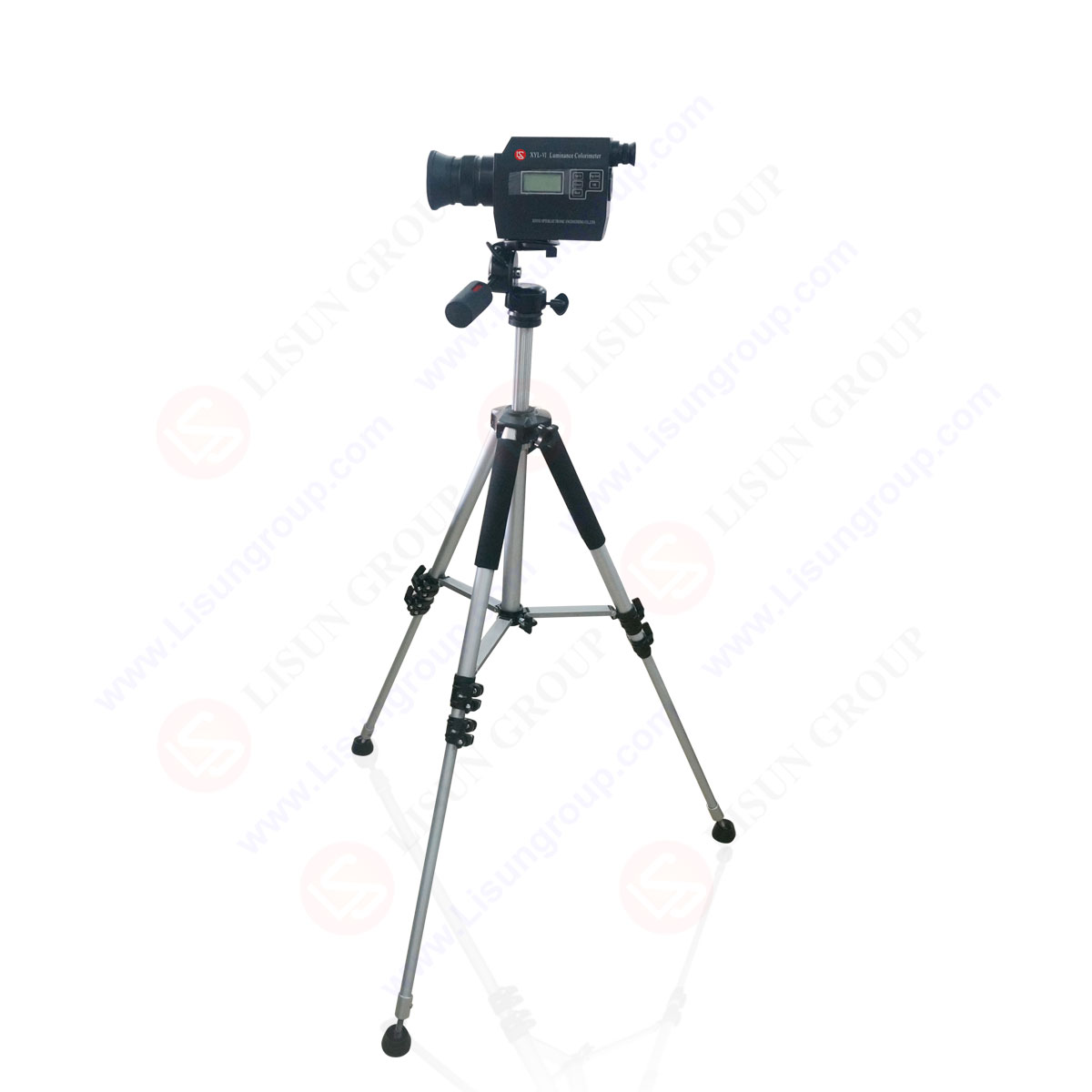
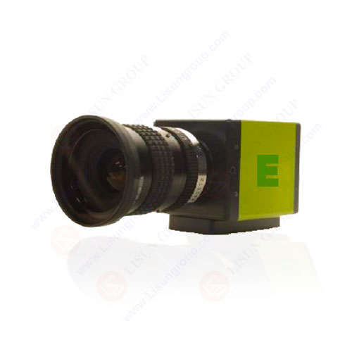
LISUN following instruments fully meet IEC 62341-6-1 Organic light emitting diode (OLED) displays -Part 6-1: Measuring methods of optical and electro-optical parameters
Your email address will not be published. Required fields are marked *

 中文简体
中文简体