LM-79 Moving Detector Goniophotometer (Mirror Type C)
LSG-6000

High Precision Rotation Luminaire Goniophotometer
LSG-1890B

High Precision Rotation Luminaire Goniospectroradiometer
LSG-1890BCCD

Goniophotometer for Automotive and Signal Lamps
LSG-1950

Goniophotometer for Traffic Signal Lamps
LSG-1950S

Compact Goniophotometer
LSG-1200A

Near Field Moving Detector Goniophotometer
LSG-1900B
Select an organization
to browse standards
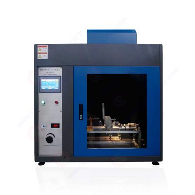
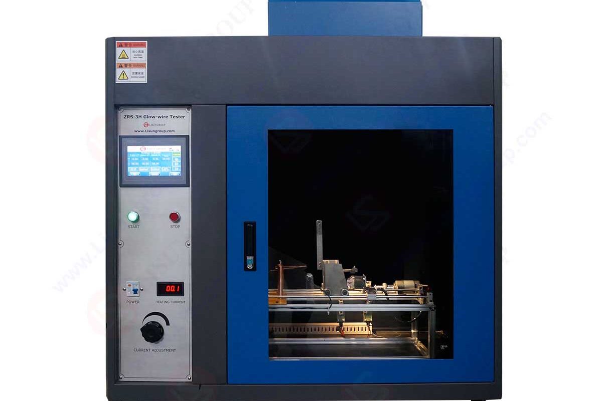
The glow wire test apparatus investigates the fire-resistant properties of raw materials and finished components. LISUN’s glow wire test equipment has been ergonomically designed to meet the above EN and IEC standards.
Fire originates from the glow wire itself. A temperature programmer is used to establish and regulate the glow-starting wire’s temperature. By switching the temperature controller to manual mode, a steady voltage signal may be sent to the glow wire, preventing the sample from experiencing a change in output power due to feedback from the control thermocouple.
What is the glow wire test?
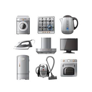
Tests for potential fire hazards in electronics, home appliances, and other electrical goods may be performed using a glow wire test apparatus. It mimics a situation in which a nearby ignition source (such as a hot element or an overloaded resistor) causes surrounding combustible materials to ignite and flame to spread rapidly, leading to the burning of insulating materials or other solid combustible materials.
Description of apparatus
Lighting equipment, low-voltage electrical appliances, electrical instruments, and other electrical and electronic items and their components are all ideal candidates for use with glow wire test apparatus in research, manufacturing, and quality inspection.
IEC 60695-2-10, UL746A, and other standards use a non-flame ignition source program, and the glow wire test equipment is used to simulate this.
Searing components or glow wires in a glow-wire testing apparatus might ignite insulating materials or other solid combustibles, causing a fire inside the device.
Components may overheat and catch fire if specific circumstances are met, such as an excess of fault current elements running through the wires or a breakdown in contact.
With modeling approaches, glow-wire testing devices can determine the potential for thermal stress induced by burning components or overload resistances in a short time. Useful for anything involving electricity or electronics, including solid electrical insulation or other solid flammable materials.

Figure: Glow wire test apparatus
Importance of Glow wire test apparatus
Since it is not always feasible to replicate identical circumstances to assess the fire dangers of electrotechnical items, the best approach to assess the fire hazards of such products is to model the real effects happening in practice as closely as possible.
It should perform a fire risk assessment on any electrotechnical equipment containing insulating material or any other solid combustible substance that might potentially spread flames within the glow wire test apparatus.
Components, wires, and even connections may catch fire if they reach a high enough temperature due to a fault current running through a wire or an overload.
To analyze the potential for a fire using a simulated method, the glow wire test device has been developed and built to measure the impact of thermal strains caused by transient heat sources like glowing components or overloaded resistors.
If a product is made using unapproved combustibles, there is a greater chance of a fire breaking out for various causes when the product is in use. That’s why using the glow-wire test for materials quality assurance is important. Some of the following situations might spark a fire in flammable materials:
Glow Wire Tester Parts
The glow wire testing device is a fire detector that employs an artificial spark as an ignition source.
Glow wire: It’s an 80/20 nickel/chromium (4mm) wire loop. The tip of the glow wire is protected by a metal that can withstand temperatures of at least 1050 degrees Celsius, and within is a tiny thermocouple with a diameter of 0.5mm that can measure the temperature of the light during continual operation up to 960 degrees Celsius.
Temperature display: The term voltage measurement device has a 1% accuracy.
Temperature control: There is a cap on the voltage that may be used to heat or cool the glow wire. After enough time for stabilization has passed, the relevant temperature is shown on the temperature display.
Weight: It allows a force of 1.2N to be delivered to the specimen as it is placed against the glow wire.
Hazard tray: Its purpose is to evaluate the risk of fire spreading from dropping glowing or burning particles from the specimen. The top layer of masonite may be easily removed and replaced if required.
Timer: Used to determine how long a specimen was exposed to a glow wire.
Specimen clamps: These have been created with minimal surface area, reducing the interference with heat displacement from the object under test.
Summary of Test Method
Preparation Before Operation of Glow-Wire Tester
It’s not simple to get reproducible results with this test, just as it is with other flammability tests. LISUN developed a glow wire test apparatus to ensure consistent results and user-friendliness. The improvements used to accomplish these objectives are shown in bold below.
Features
Main applications of glow wire tester
IEC 60335-2 is an international standard that mandates the safe operation of household appliances. The non-metallic materials used to support the current-carrying components of the appliance are put through a glow wire test to see whether they catch fire, as required by the standard.
The intensity of the glow wire test mandated by IEC 60335-1 is affected by whether or not the appliance is being monitored during operation and by how much current flows through the connection.
Vacuum cleaners, irons, and coffee makers are all examples of attended appliances that need regular monitoring. Kitchen, laundry, and dishwashing appliances are all examples of “unattended” devices since they may be left in place and operate with little human interaction.
Connectors in unsupervised applications that transfer more than 0.2A of current undergo the strictest testing. To fulfill this requirement, three levels of flammability testing must be performed:
Only contents of the envelope made from materials with a UL746A minimum flammability classification need to be checked. A needle flame test is conducted if there are parts within the package that isn’t UL746A.
Conclusion
Glow wires for home appliances are regulated by the international standard IEC 60335-2. However, the IEC 60695-2 standards document may provide the precise method and procedure for testing glow wires.
The glow wire test apparatus evaluates our light fixtures’ fire and ignition resistance. Our products will meet all your heating needs. All our light fixtures are made with highly combustible polymers.
Lisun Instruments Limited was found by LISUN GROUP in 2003. LISUN quality system has been strictly certified by ISO9001:2015. As a CIE Membership, LISUN products are designed based on CIE, IEC and other international or national standards. All products passed CE certificate and authenticated by the third party lab.
Our main products are Goniophotometer, Integrating Sphere, Spectroradiometer, Surge Generator, ESD Simulator Guns, EMI Receiver, EMC Test Equipment, Electrical Safety Tester, Environmental Chamber, Temperature Chamber, Climate Chamber, Thermal Chamber, Salt Spray Test, Dust Test Chamber, Waterproof Test, RoHS Test (EDXRF), Glow Wire Test and Needle Flame Test.
Please feel free to contact us if you need any support.
Tech Dep: Service@Lisungroup.com, Cell/WhatsApp:+8615317907381
Sales Dep: Sales@Lisungroup.com, Cell/WhatsApp:+8618117273997
There are some standards focus on specifying technical requirements and test methods for different categories of lampholders in the lighting field, ensuring their safety, compatibility, and...

LISUN’s Motor-Operated Tool | Power Tool Testing solutions strictly comply with a range of core international standards, providing full support for safety and electromagnetic compatibility (EMC)...

LISUN’s electric toy testing solutions cover IEC 62115, EN 71-1, ASTM F963 standards. Including electrical, mechanical, flammability tests to ensure toy safety compliance globally.

LISUN’s transformer test solutions meet IEC 61558-1, IEC 60076-1, IEC 62041 standards. Covering safety, performance, EMC tests, ensuring transformers comply with global requirements.

LISUN’s energy meter testing solutions align with IEC 62052-11, IEC 62053 series standards. Covering safety, electrical, environmental, and EMC tests, we help manufacturers meet global compliance...

LISUN’s audio-video communication testing solutions meet CISPR 13, IEC 60065, FCC Part 15 & EN 55032. Cover EMC, safety & performance tests for reliable AV equipment...

LISUN’s household and appliance switch testing solutions meet IEC 60669, IEC 61058, IEC 62271 standards. Covering electrical, mechanical & EMC tests for global compliance.
LISUN has all equipment according to the IEC60669 measurement, including environmental chamber, IP code waterproof dustproof test, switch lift test, etc.
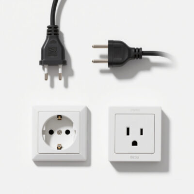
LISUN’s plugs and sockets test solutions meet IEC 60884-1, IEC 60670-1, IEC 62613-1 standards, covering electrical, mechanical and safety tests for global compliance.

LISUN provide full test solutions for HID lamp, including integrating sphere system, goniophotometer system, EMI EMC chamber, HID ballast tester, electrical safety test, etc.

Lisun can supply full test solutions for fluorescent lamp, including integrating sphere system, goniophotometer system, EMI EMC test, electronic ballast tester, electrical safety test, etc.

For the CFL design and manufactory, LISUN can supply a full quality control test solution, including photometric, colorimetric, electricity, flicker, IES candela distribution, surge test, electrical...
LISUN’s indoor and outdoor LED test solutions meet IEC 60598-1, IEC 62722-2-1, CIE 121 standards, covering safety, photometry, and environmental tests for global compliance.

 中文简体
中文简体