LM-79 Moving Detector Goniophotometer (Mirror Type C)
LSG-6000

High Precision Rotation Luminaire Goniophotometer
LSG-1890B

High Precision Rotation Luminaire Goniospectroradiometer
LSG-1890BCCD

Goniophotometer for Automotive and Signal Lamps
LSG-1950

Goniophotometer for Traffic Signal Lamps
LSG-1950S

Compact Goniophotometer
LSG-1200A

Near Field Moving Detector Goniophotometer
LSG-1900B
Select an organization
to browse standards
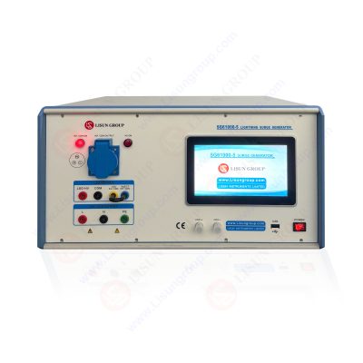
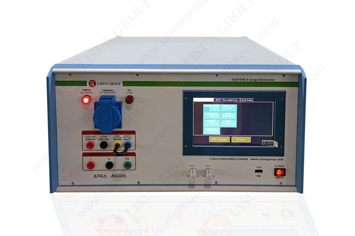
The national standard for electro-equipment surge generator is GB/T17626.5 (equivalent to international standard IEC61000-4-5).

Surge Generator SG61000 5
(1) When lightning strikes the external line, a large amount of current will flow into the external line or the ground resistance, resulting in interference voltage.
(2) Indirect lightning strikes (such as lightning between clouds or within clouds) induce voltage and current on the external line.
(3) When lightning strikes near objects, a strong electromagnetic field is set up around it, which induces voltage on the external line.
(4) When lightning strikes near the ground, interference is introduced when the ground current passes through the public grounding system.

(1) voltage interference generated by the switch of the main power supply system (such as the switch of a capacitor group);
(2)interference voltage caused by the small switch jumping near the device;
(3)switching devices with resonant line coupled;
(4)various systematic faults, such as short circuit and arcing;
Two different waveform generators are described in the standard: one is the waveform induced by lightning on the power line, and the other is the waveform induced on the communication line. Both of these lines are shielded, but the impedance of the lines varies: the waveform induced by lightning on the power line is relatively narrow (50uS) and the leading edge is sharper (1.2uS); while the waveform induced on the communication line is relatively wide, but the leading edge is smoother. In our analysis of the circuit, we mainly focus on the waveform induced by lightning on the power line, and briefly introduce the lightning protection technology of the communication line.
In the design of common mode surge suppression circuit, it is assumed that the common mode and differential mode are independent of each other. However, these two parts are not really independent, because the common mode chokes can provide a significant differential mode inductance. This differential mode inductance can be simulated by separate differential mode inductances.
In order to make use of the differential mode inductance, in the design process, the common mode and differential mode should not be designed at the same time, but should be done in a certain order. Firstly, the common mode noise should be measured and filtered out. With Differential Mode Rejection Network (DMRN), the differential mode component can be eliminated, so the common mode noise can be measured directly. If the common mode filter designed is to ensure that the differential mode noise does not exceed the allowable range at the same time, then both common mode and differential mode noise should be measured. Since the common mode component is known to be below the noise tolerance limit, only the differential mode component exceeds the limit, which can be attenuated by the differential mode leakage inductance of the common mode filter. For low-power power supply systems, the differential mode inductance of the common mode choke is sufficient to solve the differential mode radiation problem, because the source impedance of the differential mode radiation is small, so only a very small amount of inductance is effective.
For surge voltages below 4000Vp, generally only LC circuit is used for limiting and smoothing filtering, and the pulse signal is as far as possible reduced to 2-3 times of pulse signal average level. Since 50Hz power current flows through L1 and L2, inductance is easily saturated, so a common mode inductance with large leakage inductance is usually used for L1 and L2.
It is used in AC and DC, and it is often seen in power supply EMI filter, switch power supply, but seldom in DC side, which can be seen in automobile electronics. Common mode inductance is added to eliminate common mode interference on parallel lines (two lines or more). Due to the imbalance of impedance on the circuit, the common mode interference ultimately reflects on the differential mode. It is difficult to filter out by differential mode filtering method.
Lightning surge generator common mode interference is usually electromagnetic radiation, space coupled here, then whether AC or DC, you have long distance transmission, it involves common mode filtering to add common mode inductance. For example, many USB lines add rings on the line. The switch power supply input, AC power is transmitted over long distances, and it needs to be added. Usually, DC sides do not need long distance transmission and do not need to be added. Without common mode interference, adding it is a waste and has no gain on the circuit. The design of the power filter usually can be viewed from the common mode and differential mode. The most important part of the common mode filter is the common mode choke coil. Compared with the differential mode choke coil, the significant advantage of the common mode choke coil is that its inductance value is very high, and its volume is small. The important problem to be considered in designing the common mode choke coil is its leakage inductance, i.e. differential mode inductance. Generally, the way to calculate leakage inductance is to assume it is 1% of the common mode inductance. In fact, the leakage inductance is between 0.5% and 4% of the common mode inductance. When designing the optimal performance choke coil, the influence of this error may not be ignored.
Tags:SG61000-5
LISUN’s Motor-Operated Tool | Power Tool Testing solutions strictly comply with a range of core international standards, providing full support for safety and electromagnetic compatibility (EMC)...

LISUN’s electric toy testing solutions cover IEC 62115, EN 71-1, ASTM F963 standards. Including electrical, mechanical, flammability tests to ensure toy safety compliance globally.

LISUN’s transformer test solutions meet IEC 61558-1, IEC 60076-1, IEC 62041 standards. Covering safety, performance, EMC tests, ensuring transformers comply with global requirements.

LISUN’s energy meter testing solutions align with IEC 62052-11, IEC 62053 series standards. Covering safety, electrical, environmental, and EMC tests, we help manufacturers meet global compliance...

LISUN’s household and appliance switch testing solutions meet IEC 60669, IEC 61058, IEC 62271 standards. Covering electrical, mechanical & EMC tests for global compliance.
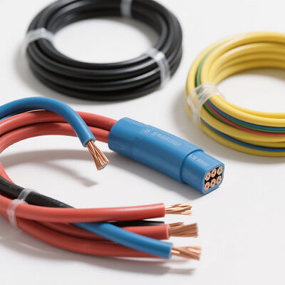
LISUN’s cable and wire test solutions meet IEC 60245-1, IEC 60227-1, IEC 60502-1 and IEC 60189 standards, covering electrical, mechanical, and safety tests for global compliance.
LISUN has all equipment according to the IEC60669 measurement, including environmental chamber, IP code waterproof dustproof test, switch lift test, etc.

Lisun can supply full test solutions for fluorescent lamp, including integrating sphere system, goniophotometer system, EMI EMC test, electronic ballast tester, electrical safety test, etc.

For the CFL design and manufactory, LISUN can supply a full quality control test solution, including photometric, colorimetric, electricity, flicker, IES candela distribution, surge test, electrical...

LISUN’s LED driver test solutions cover lab testing, online testing, EMC/EMI tests, and safety checks, meeting IEC 60335, UL 60335 standards for reliable performance evaluation.

 中文简体
中文简体