LM-79 Moving Detector Goniophotometer (Mirror Type C)
LSG-6000

High Precision Rotation Luminaire Goniophotometer
LSG-1890B

High Precision Rotation Luminaire Goniospectroradiometer
LSG-1890BCCD

Goniophotometer for Automotive and Signal Lamps
LSG-1950

Goniophotometer for Traffic Signal Lamps
LSG-1950S

Compact Goniophotometer
LSG-1200A

Near Field Moving Detector Goniophotometer
LSG-1900B
Select an organization
to browse standards
Before a product is introduced to the market, EMC testing is necessary to obtain an Electromagnetic Emission and Immunity test certification. However, the cost of performing real EMC tests is high. The product needs to be tested in an EMC pre-compliance test lab before undergoing the actual EMC test. To make sure the device will pass the EMI/EMC compliance test, pre-compliance testing will replicate every test carried out at EMI/EMC test facilities. Pre-compliance testing is less expensive and will produce results that are nearly identical to those of compliance test labs, which are very expensive and challenging to pass.
Types of EMI pre-compliance tests
Conducted and radiated emissions account for the majority of EMI test failures. The emissions can be tested using LISUNs EMI receivers. The setting up and measurement of radiated and conducted emission pre-compliance testing are explained below.

Radiated Emission Test
The radiation emission can be measured using either a near-field method or a far-field method. Understanding the distinction between near-field and far-field measurements is necessary before learning how to measure radiated emission in these fields.
A magnetic field is created when oscillating electricity flows through a conductor. The induced magnetic field also generates an electrified field. Near the product, the magnetic field has a low impedance known as a near field while the electric field has a high impedance. A far-field is one in which the electric and magnetic fields combine at the same impedance at a specific distance.
Near-Field Radiated emission test
To measure the electric field waves and magnetic field waves, a measurement probe is placed close to the circuit. The cheapest measurement method used by designers to acquire a sense of how to troubleshoot in EMI tests on their products is this one. The near-field test provides information about the EMI introduced into the device during the pre-compliance test, however it is not as precise as a far-field test.
To measure near-field tests, you will need a spectrum analyzer and measuring probes. Although there are various pricey spectrum analyzers on the market, in some circumstances a “pocket RF explorer” or USB spectrum analyzer dongle would suffice. For the signal from the probe to be amplified and sent into the spectrum analyzer in this arrangement, an RF amplifier is required.
Far-Field Radiated emission test
The emission cannot be precisely read by near-field measurement; it can only offer a rough sense of troubleshooting. Far-field radiated emission tests are therefore used in EMI/EMC test facilities. This costs money and requires some effort to set up. In pre-compliance labs, it is therefore difficult to put it up, although some EMC pre-compliance labs offer this arrangement. There are two types of locations where the far-field test can be used.
1. Open Area Site (OTAs)
The setup for the open area test is in an open space with few nearby RF reflecting objects. For the antenna to receive measurements directly from the EUT (equipment under test) and the ground’s reflection, the ground should be level and RF reflective.
EUT and the antenna should be spaced a minimum of 3 meters apart. Near field measurement, which is less precise, is used when the distance is shortened to less than 3 meters. One wavelength is 10 m for accurate readings at 30 MHz, while one wavelength is 3 m for accurate readings at 100 MHz.
2. Semi-Anechoic Chamber (SAC)
The RF-absorbing substance is embedded in the metal walls of the semi-anechoic chamber. RF signal produced by EUT is absorbed by RF absorbing material. Depending on which standard is applied to the product, the chamber’s size will vary. Typically, there is a 3m, 5m, and 10m distance between the antenna and the EUT.
Spectrum analyzer / EMI receiver
Every Lab needs a spectrum analyzer to precisely measure the RF signals, as was mentioned in the near field test. Make that the spectrum analyzer can examine all of the frequency ranges needed for EUT (e.g., 30Mhz to 5Ghz). The ability to measure “peak,” “average,” and “quasi-peak” in most spectrum analyzers aids in measuring.

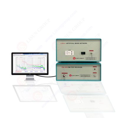
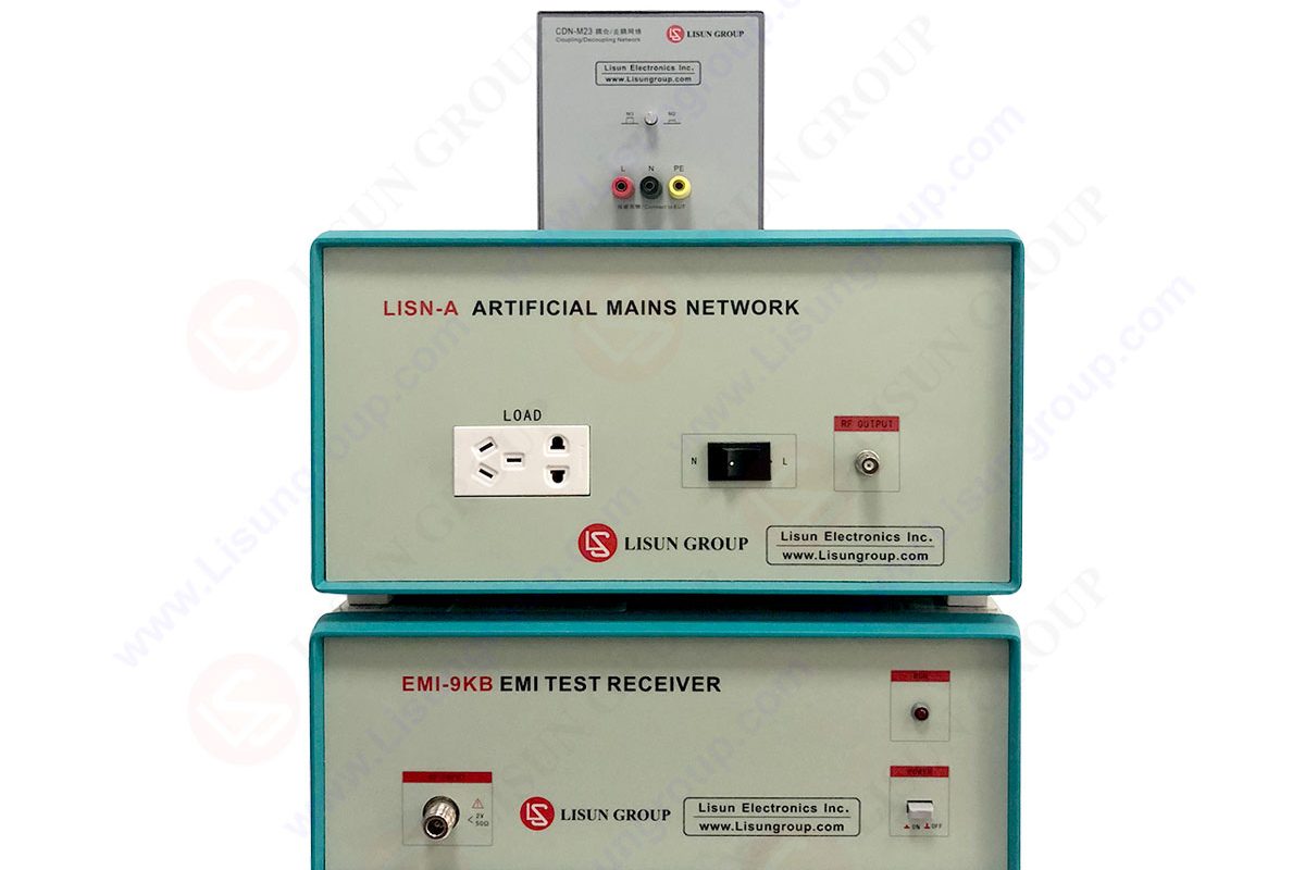
EMI-9KB EMI Test Receiver
Antenna
The antenna is the most crucial part of the far-field measurement system. The antenna size and cost will go up for lower frequency measurements while going up for higher frequency measurements. To obtain the precise antenna factors required for an accurate measurement of field strength, the antenna must be calibrated. The antenna can be raised from 4 to 6 meters in order to receive the maximum EMI signal because the signal is strongest at a specific height. Low frequency measurements cannot be made using the cheapest antenna. The PCB-based antenna used to measure frequency between 0.6GHz and 10GHz is depicted in the image below.
Conducted Emission Test
The setup and equipment needed for a conducted emission test are substantially less difficult than those for a radiated emission pre-compliance test. For the emission pre-compliance test, only a spectrum analyzer and LISN device are required. The many Spectrum analyzer alternatives for radiated emission have already been described above. Let’s now examine the functions of LISN devices.
Line impedance stabilization network, or LISN for short, is the name of the tool used for conducted emission testing. The appliance will be linked to the EUT and the supply. Measuring the RF noise produced by EUT in supply will be useful. A spectrum analyzer can be used to measure the radio frequency noise that the LISN gadget measures.
EMI/EMC Limits
The country’s EMI regulatory guidelines determine the EMI/EMC limitations. The FCC in the United States controls interference (Federal Communications Commission). The devices are divided into Classes A and B by the FCC. Devices classified as Class A are meant for industrial usage, whereas Class B devices are those meant for household use. The FCC’s Limitations for Class A and Class B devices are displayed in the table below.
The CISPR governs interference in Europe. This device is divided into two kinds as well. The categories correspond to FCC. Industrial equipment are under Class A, whereas residential devices fall under Class B. Below are the restrictions for these devices as per CISPR.
Lisun Instruments Limited was found by LISUN GROUP in 2003. LISUN quality system has been strictly certified by ISO9001:2015. As a CIE Membership, LISUN products are designed based on CIE, IEC and other international or national standards. All products passed CE certificate and authenticated by the third party lab.
Our main products are Goniophotometer, Integrating Sphere, Spectroradiometer, Surge Generator, ESD Simulator Guns, EMI Receiver, EMC Test Equipment, Electrical Safety Tester, Environmental Chamber, Temperature Chamber, Climate Chamber, Thermal Chamber, Salt Spray Test, Dust Test Chamber, Waterproof Test, RoHS Test (EDXRF), Glow Wire Test and Needle Flame Test.
Please feel free to contact us if you need any support.
Tech Dep: Service@Lisungroup.com, Cell/WhatsApp:+8615317907381
Sales Dep: Sales@Lisungroup.com, Cell/WhatsApp:+8618117273997

LISUN’s Motor-Operated Tool | Power Tool Testing solutions strictly comply with a range of core international standards, providing full support for safety and electromagnetic compatibility (EMC)...

LISUN’s transformer test solutions meet IEC 61558-1, IEC 60076-1, IEC 62041 standards. Covering safety, performance, EMC tests, ensuring transformers comply with global requirements.

LISUN’s household and appliance switch testing solutions meet IEC 60669, IEC 61058, IEC 62271 standards. Covering electrical, mechanical & EMC tests for global compliance.

LISUN provide full test solutions for HID lamp, including integrating sphere system, goniophotometer system, EMI EMC chamber, HID ballast tester, electrical safety test, etc.

Lisun can supply full test solutions for fluorescent lamp, including integrating sphere system, goniophotometer system, EMI EMC test, electronic ballast tester, electrical safety test, etc.

For the CFL design and manufactory, LISUN can supply a full quality control test solution, including photometric, colorimetric, electricity, flicker, IES candela distribution, surge test, electrical...

 中文简体
中文简体