
LM-79 Moving Detector Goniophotometer (Mirror Type C)
LSG-6000

High Precision Rotation Luminaire Goniophotometer
LSG-1890B

High Precision Rotation Luminaire Goniospectroradiometer
LSG-1890BCCD

Goniophotometer for Automotive and Signal Lamps
LSG-1950

Goniophotometer for Traffic Signal Lamps
LSG-1950S

Compact Goniophotometer
LSG-1200A

Near Field Moving Detector Goniophotometer
LSG-1900B
Select an organization
to browse standards
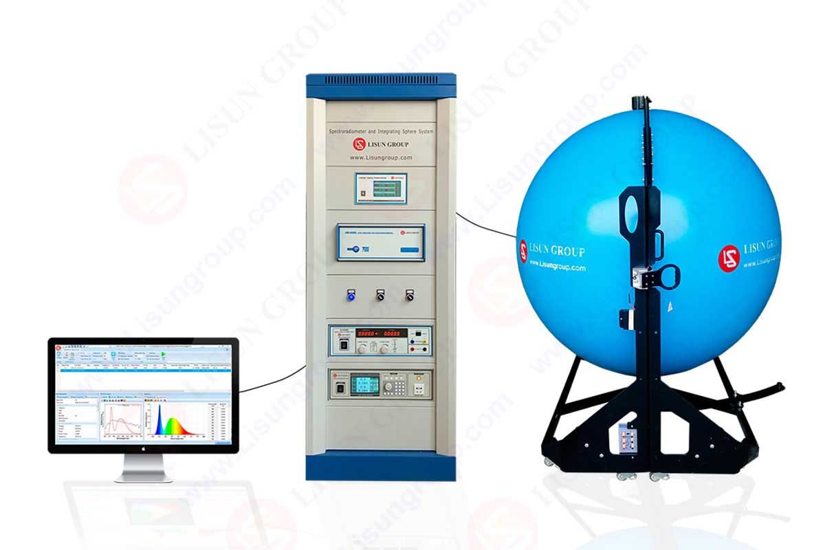
Proper light output is needed to measure and validate the output of the LED and to guarantee that the performance of the LEDs in the field is in variation with the claims on the products. Another common solution to the question of measuring the lumens of an LED is the lumen sphere (often referred to as an integrating sphere) which is a solution to the problem established by industry standards. This article describes how a lumen sphere can be used to measure total luminous flux in various LED packages, outlines useful set up and correction considerations, and identifies some of the pitfalls in the measurement of SMDs, COBs, and high-power LEDs. An example of a manufacturer of a test-equipment and the integrating spheres and photometric accessories supplied by this manufacturer are mentioned as LISUN.
A hollow sphere that has an interior that is covered with a highly diffuse reflective material is a lumen sphere. The test source is then diffusely scattered into light several times into the sphere until the brightness on the inner surface becomes virtually even. The averaged radiance measured by photodetector or spectroradiometer through a sampling port is converted to total luminous flux (lumens) by multiplying by the calibration factor of the sphere.
Key benefits:
• Captures all the luminous flux independent of the beam angle or the location distribution.
• The point sources, mini arrays, and numerous LED packages.
• Largely reduces sensitivity of alignment, relative to goniophotometers

1. insert the LED into the sphere (or feed its light through an input port).
2. Light spreads even on the lower part of the sphere.
3. The detector measures the diffuse radiance and, with the help of sphere geometry and calibration, gives the total radiant flux.
4. Radiometric units are converted into photometric units (lumens) with the help of the spectral response of the detector and human photopic response (V(λ)).
Concisely: The sphere is a combination of the angular distribution of emitted light in such a way that the directional properties of the LED are mostly irrelevant in going to measure lumens correctly, on the condition that the test is configured properly.
Repeat lumens measurement relies on proper hardware configuration:
• Input port: The location of the LED or the LED fitting. The area must be considerable not to allow the LED to look directly to the detector.
• Detector port: The photometer or spectroradiometer is put there. The detector should be calibrated and known to have a spectral responsivity.
• Baffle: It is a physical shield making it impossible to directly see the LED to the detector. A baffle in place will make sure that the detector is only reading scattered light.
• Reference lamp / calibration: This can be done with a calibrated standard lamp which can be traced to a national laboratory to measure the flux calibration factor of the sphere.
• Temperature control: LED flux is highly sensitive to the temperature of the junction. Drive current Drive-A controlled mount or thermal Test so drive current and temperature comply with real-world conditions.
Photometric measurements involve the conversion of spectral power to luminous flux by weighting by the V(λ) curve. This conversion is automatically carried out by spectroradiometers, but in photometers or non-ideal spectral response detectors, spectral mismatch occurs. Corrections are possible, in particular, those of:
• Narrow-band LEDs (e.g. deep-blue or monochromatic)
• LEDs with abnormal spectra Multi-chip RGB or phosphor-converted LEDs
These errors are minimized with the use of a spectroradiometer that has a good level of accuracy concerning the wavelength. In cases where a basic photodetector is employed, a correction factor (calculated as a result of measured SPD) should be used to make up.
The various LED packages have different measurement challenges. The following table highlights the common considerations.
| LED package type | Typical challenge in lumen-sphere measurement | Notes / mitigation |
| SMD (e.g., 2835, 5050) | Small size, directional lensing from secondary optics | Use small input port; ensure correct mounting orientation; baffle to prevent direct detector view |
| COB (Chip On Board) | High flux density and thermal coupling | Use heat-sinked mounting; allow thermal stabilization; consider radiative heating of sphere |
| High-power single LEDs | Very high radiance can saturate detector or cause local heating | Use larger sphere or attenuation, neutral-density filters; monitor detector linearity |
| LED modules / linear strips | Non-point source, sometimes long | Use larger integrating sphere or use multiple sample orientations; avoid shadowing by cables/holders |
| LED with optics (lenses, reflectors) | Optics may cause direct detector view if not baffled | Mount entire optical system as in final product; use appropriate baffle and port sizing |
• Direct detector view: Identity in estimating. It is worth placing a baffle that is just big enough to prevent direct LOS.
• Calibration drift: Regulatory recalibration with traceable standard lamps and recording calibration dates.
• Losses to non-uniform coating port or sphere: Correction factors According to the sphere manufacture and keep the sphere in good condition.
• Light leakage in the ambient air: Test in the dark (or check sealing of the sphere).
• Spectral mismatch: Measure SPD and correct or use spectroradiometer.
Adhere to international standards (such as the CIE and IES documents) on the definition of the geometry of measurements, calibration practices and reporting. Always report:
• Test current and waveform
• Case temperature (Tc) Ambient temperature (Ta).
• Reference and date of calibration.
• Instrument model and uncertainty
Reporting results and uncertainty
The appropriate measurement report must contain a total luminous flux (lumens), correlated color temperature (CCT), chromaticity coordinates (e.g. x,y) and uncertainty of measurement. Record all test conditions in order to replicate results.
Integrating spheres are the most likely to use in cases where total flux is needed without spatial distribution mapping. Equipment vendors like LISUN develop spheres or integrated measurement systems that are oriented towards photometric accuracy, thermal fixtures and easy-to-use software. An LED package type with well documented system with traceable calibration and size opposed to lighting standards will guarantee that your LED production is well tested.
Proper use of the lumen sphere renders the method of measuring lumens of various LED packages to be repeatable and traceable. By giving due consideration to mounting, thermal regulation, calibration, spectral control, and by assuring sound choice of test equipment (such as integrating sphere systems on vendors of equitable quality such LISUN), engineers and QC experts could obtain repeatable luminous flux measurements that could be used to specify products, compare with other products, and also pass regulatory examination.

LISUN provide full test solutions for HID lamp, including integrating sphere system, goniophotometer system, EMI EMC chamber, HID ballast tester, electrical safety test, etc.

Lisun can supply full test solutions for fluorescent lamp, including integrating sphere system, goniophotometer system, EMI EMC test, electronic ballast tester, electrical safety test, etc.

For the CFL design and manufactory, LISUN can supply a full quality control test solution, including photometric, colorimetric, electricity, flicker, IES candela distribution, surge test, electrical...

 中文简体
中文简体