LM-79 Moving Detector Goniophotometer (Mirror Type C)
LSG-6000

High Precision Rotation Luminaire Goniophotometer
LSG-1890B

High Precision Rotation Luminaire Goniospectroradiometer
LSG-1890BCCD

Goniophotometer for Automotive and Signal Lamps
LSG-1950

Goniophotometer for Traffic Signal Lamps
LSG-1950S

Compact Goniophotometer
LSG-1200A

Near Field Moving Detector Goniophotometer
LSG-1900B
Select an organization
to browse standards
According to the working principle of the simulated surge generator used in electromagnetic compatibility tests and lightning surge generator test, combined with the commonly used 8/20 μs and 10/700 μs test waveforms in current standards, the composition and component parameters of the discharge circuit for simulating different waveforms of surge generator can be obtained through second-order differential equations and MATLAB simulation. These findings provide analytical methods and solutions for problems encountered in surge tests.

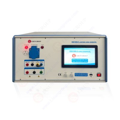
Surge Generator SG61000-5
Recent studies have shown that surge impulse observation devices, which combine computers and oscilloscopes, can record surge parameters in digital form. By using computer simulation software and nonlinear data fitting methods, numerical information can be transformed into corresponding simulated surge waveforms. Test personnel design surge generators based on the principle of capacitor charging and discharging, aiming to simulate overvoltage pulses generated by power system switches or lightning impulses. Understanding the composition and structure of the discharge circuit during the test process not only provides better control of the testing process, but also enables accurate judgment and in-depth analysis of problems encountered during the test.
First, let us define the simulated surge generator waveform. Based on the single-pulse characteristics approximating the exponential rise and fall of a lightning pulse waveform, Bruce Godle summarized the double-exponential function of lightning current waveform.
i(t)=I0k(e-at-e-βt), ( 1 )
In the formula (1), Io is the amounted to the current pulse, KA; α is attenuation before the waves
Coefficient; β is the wavetail attenuation coefficient; K is the waveform correction coefficient.
Similarly, voltage pulse waveforms can be represented
u(t)=U0A(e-t/τ1-e-t/τ2), ( 2 )
In the formula (2), U0 is the voltage pulse amounted value, KV; A is the correction coefficient;
Τ1 is a half -peak time constant; τ2 is the head time constant. Treatment of formula (1) and formula (2) can be obtained.
I t)/u (t) = k (E-AT-E-βt). (3)
Formula (3) is called a unit peak current/ voltage function equation. 8/20 μs The coefficient value corresponding to the wave shape of the 10/700 μS test.
Next, we analyzed the mathematical analysis of the 8/20 μS impact current generator discharge circuit. First, we consider the differential equation of the current pulse wave and its solution. The equivalent of the impact current generator discharge circuit is shown in Figure 1. When the geometric size of the actual circuit is far less than the wavelength of the working signal, we call it a collection of total parameter circuits. The dynamic circuit composed of an independent power supply and resistance element and dynamic components, its circuit equation is a set of differential equations. The capacitance, inductance is related to the voltage and passing of the current.

Figure 1 Impact current generator discharge circuit equivalent principle
C -Main electric container; R -circuit impedance and wave resistance; L -circuit distribution inductance value and wave resistance.
Through Kirhoff’s law, we can list the relationship between the circuit and convert the differential equation of the circuit, and then solve the system’s free response equation. Because the capacitor value is calculated from C × [P1P2 (P1-P2)] as a normalized parameter K, if the pulse current to obtain the corresponding amplitude value is to be obtained, the capacitor charging voltage must be equal to the pulse current value. However, this will increase the resistance level of charging capacitors and accelerate the aging of the capacitance. To solve this problem, in practical applications, we can appropriately increase the charging capacitor capacity through parallel capacitors and reduce the charging voltage amplitude. In addition, we can simulate through the Simulink component to obtain the discharge circuit composition and component parameters of different wave pulse waves, and to meet the standard requirements obtained by the combination of pulse waveforms. However, it should be noted that these models are established in an ideal environment, and in actual circuit design, we also need to consider the distribution parameters of components such as impedance loss, capacitance and inductors on the circuit, as well as The distributed parameters on the PEARSON coil. By fine -tuning different component parameter values, we can reach a relatively standard waveform.
In the surge test, the application of the swarming pulse observer is very important. The surge pulse observer can record the swarming parameters in a digital form through the cooperation of the computer and oscilloscope. Through the non -linear fitting of digital information, these digital information can be converted into corresponding simulation waves. The test personnel can design the surge generator according to the principle of capacitor charging and discharge, simulation the power system switch or thunderbolt impact transients generated by transients. Through the application of surging pulse observations, test personnel can not only better grasp the test process, but also accurately judge and in -depth analysis of the problems in the test.

(1) According to the component characteristics of the circuit (capacitive voltage, inductance current, etc.), the Cirhoff’s law is used to list the circuit relationship, convert the differential equation of the circuit, and solve the system’s free response equation.
(2) Because the capacitance value is calculated as a normalized parameter K by the capacitor value is to obtain the pulse current with the corresponding amplitude value, the capacitor charging voltage must be equal to the pulse current value. This will increase the resistance level of the charging capacitor and accelerate the aging of the capacitance. In practical applications, because the U0C [P1P2/(P1-P2)] is a fixed value, it can appropriately increase the charging capacitor capacity through parallel capacitors and reduce the charging voltage amplitude.
(3) Through the simulation of the Simulink component, the discharge circuit composition and component parameters of different wave pulse waves are obtained. The pulse waveform obtained by the combination meets the standard requirements. However, this is a model established in an ideal environment. In actual circuit design, it is necessary to consider the distribution parameters such as impedance loss, capacitance and inductors on the circuit, distributed parameters of the signs of the voltage of the circuit voltage, and circuit current Pearson Pearson The distributed parameters on the coil can be slightly adjusted to the values of different component to achieve a relatively standard waveform.
(4) Through the inquiry of the working principle of simulated wave surges in the electromagnetic compatibility test and lightning surge generator test, and combined with the 8/20 μs and 10/700 μs test waveforms generally performed in the current standards, the second -order differential equation can be passed through the second order. Solution and Matlab calculation simulation to obtain the composition and component parameters of different waveform simulation surge generator discharge circuits. At the same time, the use of wave pulse observations can be used to observe and record, which can better grasp the test process and accurately analyze and solve the problems encountered in the test. The application of these methods and technologies will provide effective analysis methods and solutions for problems in electromagnetic compatibility tests and lightning impact tests.

LISUN’s Motor-Operated Tool | Power Tool Testing solutions strictly comply with a range of core international standards, providing full support for safety and electromagnetic compatibility (EMC)...

LISUN’s electric toy testing solutions cover IEC 62115, EN 71-1, ASTM F963 standards. Including electrical, mechanical, flammability tests to ensure toy safety compliance globally.

LISUN’s transformer test solutions meet IEC 61558-1, IEC 60076-1, IEC 62041 standards. Covering safety, performance, EMC tests, ensuring transformers comply with global requirements.

LISUN’s energy meter testing solutions align with IEC 62052-11, IEC 62053 series standards. Covering safety, electrical, environmental, and EMC tests, we help manufacturers meet global compliance...

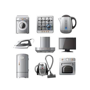
LISUN’s household and appliance switch testing solutions meet IEC 60669, IEC 61058, IEC 62271 standards. Covering electrical, mechanical & EMC tests for global compliance.
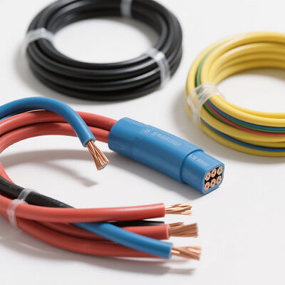
LISUN’s cable and wire test solutions meet IEC 60245-1, IEC 60227-1, IEC 60502-1 and IEC 60189 standards, covering electrical, mechanical, and safety tests for global compliance.
LISUN has all equipment according to the IEC60669 measurement, including environmental chamber, IP code waterproof dustproof test, switch lift test, etc.

Lisun can supply full test solutions for fluorescent lamp, including integrating sphere system, goniophotometer system, EMI EMC test, electronic ballast tester, electrical safety test, etc.

For the CFL design and manufactory, LISUN can supply a full quality control test solution, including photometric, colorimetric, electricity, flicker, IES candela distribution, surge test, electrical...

LISUN’s LED driver test solutions cover lab testing, online testing, EMC/EMI tests, and safety checks, meeting IEC 60335, UL 60335 standards for reliable performance evaluation.


 中文简体
中文简体