LM-79 Moving Detector Goniophotometer (Mirror Type C)
LSG-6000

High Precision Rotation Luminaire Goniophotometer
LSG-1890B

High Precision Rotation Luminaire Goniospectroradiometer
LSG-1890BCCD

Goniophotometer for Automotive and Signal Lamps
LSG-1950

Goniophotometer for Traffic Signal Lamps
LSG-1950S

Compact Goniophotometer
LSG-1200A

Near Field Moving Detector Goniophotometer
LSG-1900B
Select an organization
to browse standards
1. Introduction
With the rapid development of modern science and technology, electronics, power electronics, and electrical equipment are more and more widely used. The high-density, wide-spectrum electromagnetic signals generated by them during operation fill the entire space, forming a complex electromagnetic environment. The complex electromagnetic environment requires electronic equipment and power supplies to have higher electromagnetic compatibility. Therefore, the technology of suppressing electromagnetic interference has been paid more and more attention. Grounding, shielding and filtering are the three major measures to suppress electromagnetic interference. The following mainly introduces EMI filters used in power supplies, their basic principles and correct application methods.

2. The role of noise filters in power supply equipment
The power supply of electronic equipment, such as 220V/50Hz AC power grid or 115V/400Hz AC generator, has various EMI noises, among which man-made EMI interference sources, such as radio emissions from various radar, navigation, communication and other equipment Signals, which will induce electromagnetic interference signals on power lines and connecting cables of electronic equipment, electric rotating machinery and ignition systems, which will generate transient processes and radiated noise interference in inductive load circuits; and natural sources of interference, such as lightning The discharge phenomenon and the sky-electric interference noise in the universe, the former has a short duration but great energy, and the latter has a wide frequency range. In addition, the electronic circuit components themselves will also generate thermal noise when they work.
These electromagnetic interference noises, through radiation and conduction coupling, can affect the normal operation of various electronic devices operating in this environment.
All kinds of regulated power supply itself is also a source of electromagnetic interference. In the linear regulated power supply, the unidirectional pulsating current formed by rectification can also cause electromagnetic interference; the switching power supply has the advantages of small size and high efficiency, and is more and more widely used in modern electronic equipment, but because it is used in power conversion when it is in the switching state, it is a strong EMI noise source, and the EMI noise it produces has a wide frequency range and a high intensity. These electromagnetic interference noises also pollute the electromagnetic environment through radiation and conduction, thereby affecting the normal operation of other electronic devices.
For electronic equipment, when EMI noise affects analog circuits, the signal-to-noise ratio of signal transmission will deteriorate, and in severe cases, the signal to be transmitted will be overwhelmed by EMI noise and cannot be processed. When EMI noise affects digital circuits, it can cause errors in logic relationships, leading to erroneous results.
For the power supply equipment, in addition to the power conversion circuit, there are driving circuits, control circuits, protection circuits, input and output level detection circuits, etc., and the circuits are quite complex. These circuits are mainly composed of general-purpose or special-purpose integrated circuits. When a malfunction occurs due to electromagnetic interference, the power supply will stop working, causing the electronic equipment to fail to work normally. The grid noise filter can effectively prevent the power supply from malfunctioning due to external electromagnetic noise interference.

The role of noise filters in power supply equipment

Basic circuit diagram of power filter
In addition, a part of the EMI noise entering from the power supply input end can appear at the output end of the power supply, and it will generate an induced voltage in the load circuit of the power supply, which becomes the reason for the circuit to malfunction or interfere with the transmission signal in the circuit. These problems can also be prevented with noise filters.
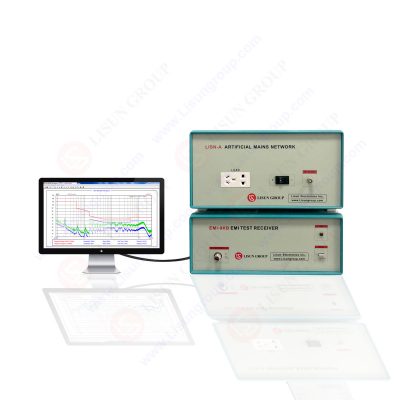
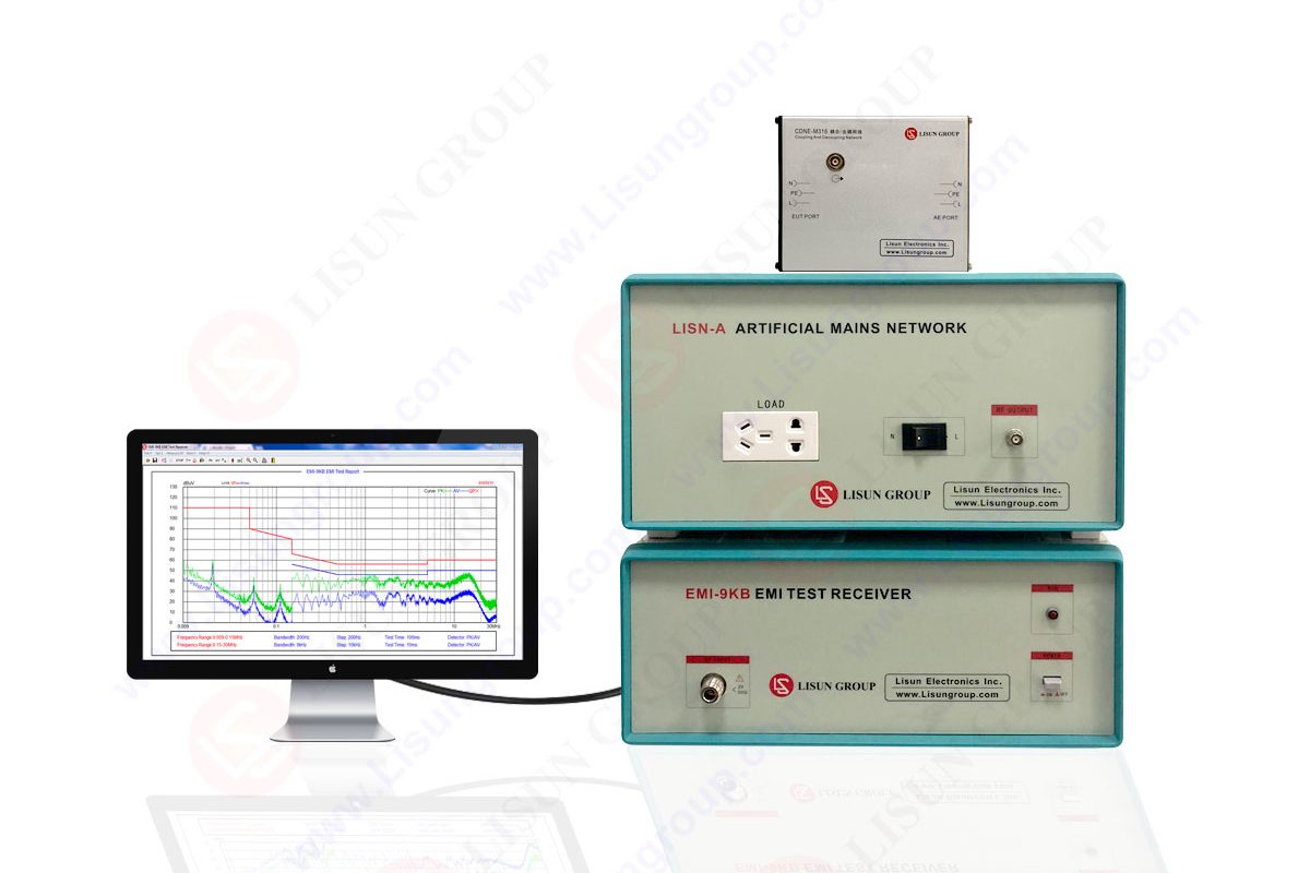
LISUN EMI receiver system for EMI (Electromagnetic Interference) radiation conduction or conducted emissions testing. The EMI-9KB EMI receiver is produced by the full closure structure and strong electro-conductibility material, which has high shielding effect. Due to the new technology for the EMI Test System, it solved the instrument self-EMI problem. The test results are according to the international format test report. The EMI Test System EMI-9KB fully meets CISPR15:2018, CISPR16-1, GB17743, FCC, EN55015 and EN55022.

EMI-9KB EMI Test Receiver
The role of noise filters in power supply equipment is as follows:
(1) Prevent external electromagnetic noise from interfering with the work of the control circuit of the power supply equipment itself;
(2) Prevent external electromagnetic noise from interfering with the work of the load of the power supply;
(3) Suppress the EMI generated by the power supply itself;
(4) Suppress EMI generated by other equipment and propagated through the power supply.
When the switching power supply itself is working and the electronic equipment is in the switching state, terminal noise will appear at the input end of the power supply equipment, resulting in radiation and conduction interference, and will also enter the AC power grid to interfere with other electronic equipment, so effective measures must be taken to suppress it. . Electromagnetic shielding is the best way to suppress radiated interference from EMI noise. In terms of suppressing the conducted interference of EMI noise, the use of EMI filters is a very effective means, and of course, good grounding measures should be used.
Various countries in the world have implemented strict electromagnetic noise limit rules, such as the United States has FCC, Germany has FTZ, VDE and other standards. If the electronic equipment does not meet the noise limit rules, the product cannot be sold and used.
Due to the above reasons, it is necessary to design and use a grid noise filter that meets the requirements in the power supply equipment.
3. Types of EMI Noise and Filters
There are two types of EMI noise on the power supply input leads: common-mode noise and differential-mode noise, as shown in Figure 1. The EMI noise existing between the AC input lead and the ground is called its common mode noise. It can be regarded as the interference signal with the same potential and the same phase transmitted on the AC input line, that is, the voltages V1 and V2 in Figure 1. The EMI noise existing between the AC input leads is called differential mode noise, which can be regarded as an interference signal with a phase difference of 180° transmitted in the AC input line, namely the voltage V3 in Figure 1. Common mode noise is the interference current flowing into the ground from the AC input line, and differential mode noise is the interference current flowing between the AC input lines. Conducted EMI noise on any power input line can be represented by common mode and differential mode noise, and these two EMI noises can be treated as independent EMI sources to be suppressed separately.
When taking measures to suppress electromagnetic interference noise, the main consideration should be to suppress common mode noise, because common mode noise occupies a major part in the whole frequency domain, especially in the high frequency domain, and differential mode noise accounts for a large proportion in the low frequency domain, so it should be based on This characteristic of EMI noise is used to select an appropriate EMI filter.
Noise filters for power supplies can be divided into integrated and discrete types according to their shapes. The integrated type is to encapsulate the inductor coil, capacitor, etc. in a metal or plastic shell; the discrete type is to install the inductor coil, capacitor, etc. on the printed board to form a noise suppression filter. Which form to use depends on cost, characteristics, installation space, etc. The integrated type has high cost, good characteristics and flexible installation; the discrete type has lower cost, but the shielding is not good, and can be freely distributed on the printed board.
4. The basic structure of the noise filter
The power supply EMI noise filter is a passive low-pass filter, which transmits the alternating current to the power supply without attenuation, and greatly attenuates the EMI noise introduced with the alternating current. They enter the AC grid and interfere with other electronic equipment.
The basic structure of the single-phase AC grid noise filter is shown in Figure 2. It is a four-terminal passive network composed of centralized parameter components. The main components used are common mode inductor coils L1, L2, differential mode inductors L3, L4, common mode capacitors CY1, CY2 and differential mode capacitors CX. If this filter network is placed at the input end of the power supply, L1 and CY1 and L2 and CY2 respectively form a low-pass filter between two pairs of independent ports on the AC incoming line, which can attenuate the common mode interference existing on the AC incoming line. noise, preventing them from entering the power supply. The common mode inductance coil is used to attenuate the common mode noise on the AC incoming line. L1 and L2 are generally wound with the same number of turns in the same direction on the ferrite core of the closed magnetic circuit. The magnetic fluxes generated by the alternating currents in the two coils cancel each other out, so that the magnetic cores do not saturate the magnetic fluxes, and the inductance values of the two coils are larger and remain unchanged in the common mode state.
The differential mode inductance coils L3, L4 and the differential mode capacitor CX form a low-pass filter between the independent ports of the AC incoming line, which is used to suppress the differential mode interference noise on the AC incoming line and prevent the power supply equipment from being interfered by it.
The power supply noise filter shown in Figure 2 is a passive network with bidirectional rejection. Inserting it between the AC power grid and the power supply is equivalent to adding a blocking barrier between the EMI noise of the two. Such a simple passive filter acts as a two-way noise suppression, so it can be used in various electronic equipment. has been widely used.
5. Main design principles of noise filters
The magnetic cores used in common mode inductance coils are toroidal, E-shaped and U-shaped. The material is generally ferrite. The toroidal core is suitable for large current and small inductance. Its magnetic circuit is longer than E-shaped and U-shaped, and there is no gap. , a larger inductance can be obtained with a smaller number of turns, and because of these characteristics, it has better frequency characteristics. The coil leakage flux of the E-shaped magnetic core is small, so when the leakage magnetic flux of the inductance may affect other circuits or other circuits have magnetic coupling with the common mode inductance, and the required noise attenuation effect cannot be obtained, the E-shaped magnetic core should be considered. common mode inductance.
Differential mode inductance coils generally use metal powder-pressed magnetic cores. Due to the low frequency range of powder-pressed magnetic cores, from tens of kHz to several MHz, its DC overlap characteristics are good, and the inductance will not drop significantly in high current applications. Best suited for differential mode inductors.
In Figure 2, the power supply noise filter uses two kinds of capacitors, CX, CY1 and CY2. They have different functions in the filter and have different safety level requirements, so their performance parameters are directly related to the safety performance of the filter.
The differential mode capacitor CX is connected to both ends of the AC incoming line. In addition to the rated AC voltage, it will also superimpose various EMI peak voltages that exist between the AC incoming lines. Therefore, the performance requirements of the capacitor’s withstand voltage and transient peak voltage are relatively high, and at the same time, it is required that after the capacitor fails, the subsequent circuit and personal safety cannot be endangered. The safety levels of CX capacitors are divided into two categories: X1 and X2. The X1 type is suitable for general occasions, and the X2 type is suitable for applications where high noise peak voltage occurs.
The common mode capacitor CY is connected between the AC incoming line and the chassis ground. They are required to have a sufficient safety margin in terms of electrical and mechanical properties. In case of a breakdown and short circuit, the equipment chassis will be dangerous. If the insulation or grounding protection of the equipment fails, the operator may suffer electric shock and even endanger personal safety. Therefore, the capacity of the CY capacitor should be limited so that the leakage current under the voltage of the rated frequency is less than the safe specification value. In addition, it is also required that it should have sufficient withstand voltage and transient high peak voltage margin, and in case of voltage breakdown, it should be in an open-circuit state, so that the equipment casing will not be charged.
To sum up, when designing and selecting grid noise filters, the safety performance of the inductors and capacitors used must be considered first because they work in high voltage, high current, and harsh electromagnetic interference environments. For the inductance coil, its magnetic core, winding material, insulation material and insulation distance, coil temperature rise, etc. should be paid attention to. For capacitors, the type of capacitance, withstand voltage, safety level, capacity, leakage current, etc. should be given priority, and it is especially required to select products that have passed the safety certification of international safety agencies.
4) To sum up, the following points should be paid attention to when using the power supply noise filter:
a. The filter should be installed as close as possible to the AC inlet of the equipment, and the AC incoming line without the filter should be as short as possible in the equipment;
b. The capacitor leads in the filter should be as short as possible to prevent the lead inductive and capacitive reactance from resonating at lower frequencies;
c. There is a large current flowing on the grounding wire of the filter, which will generate electromagnetic radiation. The filter should be well shielded and grounded;
d. The input line and output line of the filter cannot be bundled together. When wiring, try to increase the distance between them to reduce the coupling between them. A partition or shielding layer can be added.
6. Conclusion
The design and selection of electromagnetic interference filters are mainly based on the noise interference characteristics and the requirements of system electromagnetic compatibility, on the basis of understanding the frequency range of electromagnetic interference and estimating the approximate magnitude of the interference. First of all, it is necessary to understand the use environment of the filter (use voltage, load current, ambient temperature and humidity, vibration shock, installation method and location, etc.), and focus on its safety performance parameters, because it is related to equipment and personal safety. Also make the filter produce the best suppression of EMI noise. The network structure and parameters of the filter should be selected according to the requirements of the access circuit and the principle of producing the largest impedance mismatch. For optimum electromagnetic noise attenuation characteristics, the filter should be properly mounted on the electronic equipment.
Lisun Instruments Limited was found by LISUN GROUP in 2003. LISUN quality system has been strictly certified by ISO9001:2015. As a CIE Membership, LISUN products are designed based on CIE, IEC and other international or national standards. All products passed CE certificate and authenticated by the third party lab.
Our main products are Goniophotometer, Integrating Sphere, Spectroradiometer, Surge Generator, ESD Simulator Guns, EMI Receiver, EMC Test Equipment, Electrical Safety Tester, Environmental Chamber, Temperature Chamber, Climate Chamber, Thermal Chamber, Salt Spray Test, Dust Test Chamber, Waterproof Test, RoHS Test (EDXRF), Glow Wire Test and Needle Flame Test.
Please feel free to contact us if you need any support.
Tech Dep: Service@Lisungroup.com , Cell/WhatsApp:+8615317907381
Sales Dep: Sales@Lisungroup.com , Cell/WhatsApp:+8618117273997

LISUN’s Motor-Operated Tool | Power Tool Testing solutions strictly comply with a range of core international standards, providing full support for safety and electromagnetic compatibility (EMC)...

LISUN’s transformer test solutions meet IEC 61558-1, IEC 60076-1, IEC 62041 standards. Covering safety, performance, EMC tests, ensuring transformers comply with global requirements.

LISUN’s household and appliance switch testing solutions meet IEC 60669, IEC 61058, IEC 62271 standards. Covering electrical, mechanical & EMC tests for global compliance.

LISUN provide full test solutions for HID lamp, including integrating sphere system, goniophotometer system, EMI EMC chamber, HID ballast tester, electrical safety test, etc.

Lisun can supply full test solutions for fluorescent lamp, including integrating sphere system, goniophotometer system, EMI EMC test, electronic ballast tester, electrical safety test, etc.

For the CFL design and manufactory, LISUN can supply a full quality control test solution, including photometric, colorimetric, electricity, flicker, IES candela distribution, surge test, electrical...

 中文简体
中文简体