LM-79 Moving Detector Goniophotometer (Mirror Type C)
LSG-6000

High Precision Rotation Luminaire Goniophotometer
LSG-1890B

High Precision Rotation Luminaire Goniospectroradiometer
LSG-1890BCCD

Goniophotometer for Automotive and Signal Lamps
LSG-1950

Goniophotometer for Traffic Signal Lamps
LSG-1950S

Compact Goniophotometer
LSG-1200A

Near Field Moving Detector Goniophotometer
LSG-1900B
Select an organization
to browse standards
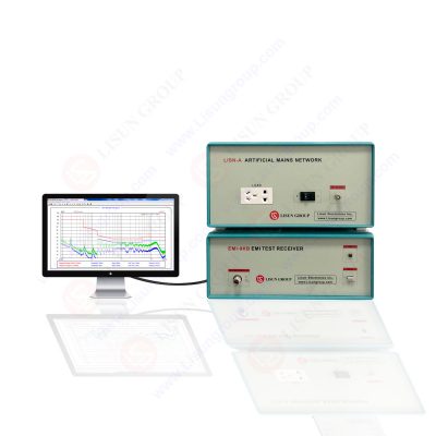
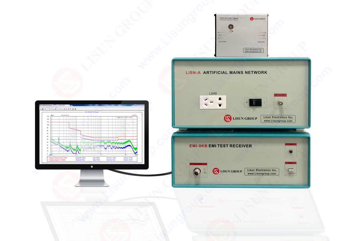
Electromagnetic Interference (EMI) Testing is electronic noise that interferes with cable signals and reduces signal integrity. EMI is typically generated by sources of electromagnetic radiation such as motors and machines. Electromagnetic interference is an electromagnetic phenomenon that has been discovered for a long time. It was discovered almost at the same time as the phenomenon of electromagnetic effect. In 1881, British scientist Heaviside published an article “On Interference”, which marked the beginning of research on interference. In 1889, the British post and telecommunications department studied the interference problem in communication, which made the research on the interference problem begin to move towards engineering and industrialization.
 Testing 1")
EMI-9KB EMI Test Receiver
1. Classification of electromagnetic interference
There are many ways to classify interference sources.
1.1. Generally speaking, electromagnetic interference sources are divided into two categories: natural interference sources and man-made interference sources.
Natural sources of interference mainly come from the sky-electric noise in the atmosphere and the cosmic noise in the outer space of the earth. They are both an essential element of the Earth’s electromagnetic environment and a source of interference to radio communications and space technology. Natural noise can interfere with the operation of satellites and spacecraft, as well as with the launch of ballistic missile launch vehicles.
The source of man-made interference is the electromagnetic energy interference generated by electromechanical or other artificial devices, some of which are devices specially used to emit electromagnetic energy, such as radio equipment such as radio, television, communication, radar and navigation, which are called intentionally emitted interference sources. The other part is the emission of electromagnetic energy while completing its own functions, such as traffic vehicles, overhead power lines, lighting fixtures, electrical machinery, household appliances, and industrial and medical radio frequency equipment. Therefore, this part becomes a source of unintentional emission of interference.
 Testing - LISUN")
1.2. According to the properties of electromagnetic interference, it can be divided into functional interference sources and non-functional interference sources.
Functional interference sources refer to the direct interference to other equipment caused by the realization of functions of the equipment; non-functional interference sources refer to the accompanying or additional side effects of electrical devices while realizing their own functions. Such as arcing interference generated by switch closure or cut-off.
1.3. From the spectrum width of electromagnetic interference signal, it can be divided into broadband interference source and narrowband interference source. They are distinguished with respect to the bandwidth of the given receptors being larger or smaller. If the bandwidth of the interference signal is larger than the bandwidth of the specified receptor, it becomes a broadband interference, otherwise it is called a narrowband interference source.
1.4. According to the frequency range of the interference signal Interference sources can be divided into power frequency and audio interference sources (50Hz and its harmonics), very low frequency interference sources (below 30Hz), carrier frequency interference sources (10kHz~300kHz), radio frequency and video interference sources (300kHz), microwave interference source (300MHz~100GHz).
 Testing 2")
electromagnetic interference signal
2. Electromagnetic interference way
There are generally two ways of electromagnetic interference propagation: conduction coupling and radiation coupling. The occurrence of any electromagnetic interference must have the transmission and transmission path (or transmission channel) of the interference energy. It is generally believed that there are two ways of electromagnetic interference transmission: one is conduction transmission; the other is radiation transmission. Therefore, from the perspective of the interfered sensor, the interference coupling can be divided into two categories: conduction coupling and radiation coupling.
Conducted transmission must have a complete circuit connection between the interference source and the sensor, and the interference signal is transmitted to the sensor along this connection circuit, and the interference phenomenon occurs. This transmission circuit may include wires, conductive members of the device, power supplies, common impedances, ground planes, resistors, inductors, capacitors, and mutual inductance elements, among others.
Radiation transmission is propagating through the medium in the form of electromagnetic waves, and the interference energy is emitted to the surrounding space according to the law of the electromagnetic field. There are three common types of radiation coupling: 1. The electromagnetic wave emitted by antenna A is accidentally accepted by antenna B, which is called antenna-to-antenna coupling; 2. The electromagnetic field in space is coupled by wire induction, which is called field-to-line coupling; 3. Two The induction of high-frequency signals between parallel wires is called line-to-line inductive coupling.
In practical engineering, interference between two devices usually involves coupling in many ways. It is precisely because of the simultaneous existence of multiple ways of coupling, repeated cross-coupling, and common interference that electromagnetic interference becomes difficult to control.
3. Electromagnetic Interference Elimination Method
(1) Use shielding technology to reduce electromagnetic interference. In order to effectively suppress the radiation and conduction of electromagnetic waves and the noise current caused by higher harmonics, shielded cables must be used for elevator motor cables driven by frequency converters, and the conductance of the shielding layer is at least 1/10 of the electrical wires of each phase conductor core. , and the shielding layer should be grounded reliably. It is best to use shielded cables for control cables; double-shielded twisted-pair cables should be used for analog signal transmission lines; different analog signal lines should be routed independently and have their own shielding layers. In order to reduce the coupling between lines, do not put different analog signals in the same common return line; it is best to use double-shielded twisted-pair cables for low-voltage digital signal lines, or single-shielded twisted-pair cables can be used. Transmission cables for analog signals and digital signals should be shielded separately and traces should be short.
(2) Use grounding technology to eliminate electromagnetic interference. To ensure that all equipment in the elevator control cabinet is well grounded, and thick grounding wire. Connect to the power inlet grounding point (PE) or the grounding busbar. It is especially important that any electronic control equipment connected to the frequency converter is co-grounded with it, and short and thick wires should be used for co-grounding. At the same time, the ground wire of the motor cable should be directly grounded or connected to the ground terminal (PE) of the inverter. The above grounding resistance value should meet the requirements of relevant standards.
(3) Use wiring technology to improve electromagnetic interference. The motor cable should be routed independently of other cables, and the long-distance parallel route between the motor cable and other cables should be avoided to reduce the electromagnetic interference caused by the rapid change of the output voltage of the inverter; They cross at a 90° angle and the shields of the motor and control cables must be fastened to the mounting plate with suitable clips.
(4) Use filtering technology to reduce electromagnetic interference. Line reactors are used to reduce the harmonics generated by the frequency converter, and can also be used to increase the impedance of the mains and help absorb surge voltages and mains spikes when nearby equipment is put into operation. The incoming line reactor is connected in series between the power supply and the power input terminal of the inverter. When the situation of the main power grid is unknown, it is better to add a line reactor. In the above circuit, a low-pass frequency filter (the same for FIR below) can also be used, and the FIR filter should be connected in series between the incoming line reactor and the inverter. For elevator inverters running in a noise-sensitive environment, the use of FIR filters can effectively reduce the radiation interference from the inverter conduction.
(5) In the scene where the interference of the lighting line, the interference of the motor feedback is too large, and the power line of the system is disturbed, the communication interference cannot be eliminated by the above grounding, and the magnetic ring can be used to suppress the interference. The magnetic ring is added in the following order: Until the communication returns to normal: 1. If the two power lines of the lighting are disconnected at the same time, and the communication returns to normal, please add a magnetic ring to the two lines of the lighting under the control cabinet, and wind it three times (aperture 20 to 30, thickness 10, length 20 or so magnetic rings). If disconnecting the lighting line has no effect, it means that the lighting line does not interfere with communication, and no treatment is required. 2. Add a magnetic ring on the communication lines C+ and C- from the outlet of the main board, and wrap it around once. Note that it can only be wound once. After more winding, the car communication display will become better, but most of the effective signals from the car are filtered out, resulting in the failure to register the car’s internal selection. 3. Add a magnetic ring to the 24V power supply and 0V ground output from the main board to the car and elevator, and wind it for 2 to 3 turns. 4. Add a magnetic ring to each of the three-phase lines between the running contactor and the motor and wrap one circle. After the above method is used to increase the magnetic ring, it can deal with the on-site power supply, motor and lighting interference.
(6) Selection of magnetic ring material: According to the frequency characteristics of the interference signal, nickel-zinc ferrite or manganese-zinc ferrite can be selected, and nickel-zinc ferrite or manganese-zinc ferrite can be selected. The high-frequency characteristics of the former are better than the latter. The magnetic permeability of manganese-zinc ferrite is in the thousands—tens of thousands, while the permeability of nickel-zinc ferrite is in the hundreds—tens of thousands. The higher the permeability of the ferrite, the higher the impedance at low frequencies and the lower the impedance at high frequencies. Therefore, when suppressing high-frequency interference, nickel-zinc ferrite should be used. Otherwise, manganese-zinc ferrite should be used. Or put manganese-zinc and nickel-zinc ferrite on the same bundle of cables at the same time, so that the interference frequency band that can be suppressed is wider. Size selection of the magnetic ring: The greater the difference between the inner and outer diameters of the magnetic ring, the greater the longitudinal height, and the greater the impedance, but the inner diameter of the magnetic ring must be tightly wrapped with cables to avoid magnetic leakage. The installation position of the magnetic ring: The installation position of the magnetic ring should be as close as possible to the interference source, that is, it should be close to the inlet and outlet of the cable.
Lisun Instruments Limited was found by LISUN GROUP in 2003. LISUN quality system has been strictly certified by ISO9001:2015. As a CIE Membership, LISUN products are designed based on CIE, IEC and other international or national standards. All products passed CE certificate and authenticated by the third party lab.
Our main products are Goniophotometer, Integrating Sphere, Spectroradiometer, Surge Generator, ESD Simulator Guns, EMI Receiver, EMC Test Equipment, Electrical Safety Tester, Environmental Chamber, Temperature Chamber, Climate Chamber, Thermal Chamber, Salt Spray Test, Dust Test Chamber, Waterproof Test, RoHS Test (EDXRF), Glow Wire Test and Needle Flame Test.
Please feel free to contact us if you need any support.
Tech Dep: Service@Lisungroup.com, Cell/WhatsApp:+8615317907381
Sales Dep: Sales@Lisungroup.com, Cell/WhatsApp:+8618117273997

LISUN’s Motor-Operated Tool | Power Tool Testing solutions strictly comply with a range of core international standards, providing full support for safety and electromagnetic compatibility (EMC)...

LISUN’s transformer test solutions meet IEC 61558-1, IEC 60076-1, IEC 62041 standards. Covering safety, performance, EMC tests, ensuring transformers comply with global requirements.

LISUN’s household and appliance switch testing solutions meet IEC 60669, IEC 61058, IEC 62271 standards. Covering electrical, mechanical & EMC tests for global compliance.

LISUN provide full test solutions for HID lamp, including integrating sphere system, goniophotometer system, EMI EMC chamber, HID ballast tester, electrical safety test, etc.

Lisun can supply full test solutions for fluorescent lamp, including integrating sphere system, goniophotometer system, EMI EMC test, electronic ballast tester, electrical safety test, etc.

For the CFL design and manufactory, LISUN can supply a full quality control test solution, including photometric, colorimetric, electricity, flicker, IES candela distribution, surge test, electrical...

 中文简体
中文简体