LM-79 Moving Detector Goniophotometer (Mirror Type C)
LSG-6000

High Precision Rotation Luminaire Goniophotometer
LSG-1890B

High Precision Rotation Luminaire Goniospectroradiometer
LSG-1890BCCD

Goniophotometer for Automotive and Signal Lamps
LSG-1950

Goniophotometer for Traffic Signal Lamps
LSG-1950S

VAD Fire Alarm Visual Alert Device Goniophotometer
LSG-1930

Compact Goniophotometer
LSG-1200A

LED Goniophotometer
LSG-1100
 LEDs and Luminaire Test Solutions
 LM-79 and LM-80 Test Solutions
 LED Driver Test Solutions
 Household Appliances Test Solutions
 Mobile and Network Test Solutions
 Automotive Electronics Test Solutions
 Audio-Video and IT Test Solutions
 Cable and Wire Test Solutions
 Plugs and Sockets Test Solutions
 Power Switch Test Solutions
 Transformer Test Solutions
 Electric Toys Test Solutions
 Energy Meter Test Solutions
 Motor-Operated Tool Test Solutions
Select an organization
to browse standards
Impulse voltage generator is one of the basic instruments used to test the insulation strength of high voltage equipment with transient conditions. In contrast to steady state tests (AC or DC) in impulse testing, transient elevated events produced by lightning strikes switching operations and faults of an electrical system are reproduced. These incidences cause severe electrical loads within very brief periods of time and normally control insulation design limits. This is why impulse testing is a required element of the qualification of transformers bushings cables switchgear arresters and other high voltage assets.
In real world laboratories the impulse voltage generator is often compared with a high voltage surge generator of EMC immunity testing. Although both systems generate transient voltages the goals and the nature of the waveforms is different. Insulation evaluation is dedicated to streams of censorship breakdown behavior streamer development and withstand capacity of standard impulse-shapes instead of equipment immunity. The mechanism behind the way the impulse generators are built and the working principle would be vital in generating some useful data on the insulation strength.
The impulse voltage testing is based on the use of standardized definitions of waveforms that portray reality in the transient world. The most prevalent is the lightning impulse waveform that has a steep front time and slower decay time usually denoted in microseconds 1.2 microseconds to crest and 50 microseconds to half value. Switching impulse waveforms are longer-rise-and-decay period waveforms with applications in ultra high voltage devices where lightning compares to switching incidents.
Every one of these waveforms is caused by an impulse voltage generator that charges a capacitor bank to a specified voltage and then discharges it to a wave shaping network of resistors and capacitance. The arrangement regulates the front and rear of the impulse. A common reason that Marx generator configurations are so popular was that they could easily stack relatively low charging voltages in series during discharge in order to produce extremely high output voltages.
The stray capacitance inductance and resistance in the design of generators should be taken into consideration, and these distort the waveform. These parasitic elements become stronger with the increase in the voltage levels. Scrupulous physical design and choice of components is thus involved in the ensuring that the delivered impulse as of standard tolerances. This is opposed to a general purpose high voltage surge generator which is used to test EMC impulse systems EMC impulse systems are optimized at waveform fidelity at very high voltage, not repetition rate or automation.
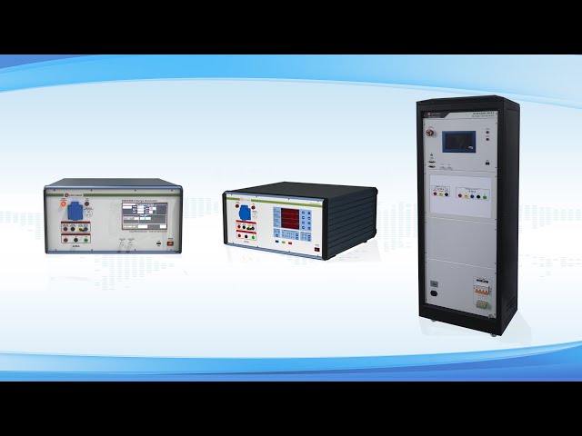
The determination of the strength of insulation does not merely involve generating an impulse. The circuit arrangement of the tests determines the arrangement of the stress and identifies the failure of the circuit. The impulse voltage generator is connected to high voltage equipment by test leads that are aimed at reducing corona and partial discharge. Effective clearance and shielding avoid flashover outside the test object that would invalidate results.
They are usually measured with capacitive or resistive voltage dividers to high band oscilloscopes. These dividers should be calibrated and impulse response designed (to ensure they reproduce the fast front without being too much stuck or attenuated). Existing measurements can also be applied in case of the breakdown initiation identification or discharge behavior analysis in case of flashover.
Earthing and grounding are important. The grounding or back circuit should also be low impedance and sharp to prevent reflections which distort the shape of the impulse. The poor grounding of the ground plain and the bonding is a cost of small factories due to the ground-related measurement errors and the inherent risk of safety failures in the test laboratories. Unlike EMC surge testing where coupling networks are used to specify impedance condition testing depends on free field configurations and smart physical geometry.
Impulse testing procedures undergo standardization so that they can be compared among the laboratories. An example of a test sequence is normally proceeding to apply a series of impulses at the voltage levels incrementing until the required test voltage. The insulation will be such that it centers around a fixed number of impulses before it breaks. It uses both positive and negative polarity impulses since polarity does affect the development and the strength of the streamers.
There is a difference in evaluation criterion between internal breakdown and external flashover. In some situations, external flashover in air or on the surfaces can be acceptable as long as it does not ruin the equipment. Failure happens as a result of internal failure in solid or liquid insulation. Acoustic signals and a waveform analysis useful in the visual examination aid in determining the type of event.
Conditioning is also observed when it comes to repeated use of impulses. There are ones that become stronger following initial impulses as a result of drying or charge redistribution whereas others deteriorate steadily. The documentation of the parameters of waveforms and breakdown behaviour throughout the sequence gives knowledge of the quality of the insulation and consistency of the production process.
The operation of an impulse voltage generator has practical issues which are unlike the ones arising with the operation of a high voltage surge generator in testing of EMC. Impulse systems have much higher voltage ratings, and usually have lower frequencies of repetition, and have greater clearance and safety margins. The setup time and operator know-how hence form an important element.
Waveform check is more challenging as, at hundreds of kilovolts, special dividers and oscilloscopes are needed. Air breakdown behavior is determined by the environment condition which includes humidity pressure and temperature and should be recorded. The variables are not as critical in EMC surge testing where voltages are smaller and the equipment is enclosed.
With this change there exist conceptual overlap. Impulse and surge generators are both based on regulated discharge of energy and shaping the waveforms. Complementary systems with similar design philosophy and safety ideas are often supplied by different laboratories equipment suppliers. Such companies like LISUN provide high voltage and surge testing, which can serve as assistance to the laboratory operating in the field of insulation assessment and EMC without violating the requirements.
Tests of impulse voltage generators go straight into insulation coordination decision-making. Resistance established during the laboratory guides design clearance of protection devices choice and safety margins of power systems. Test results are compared with estimated overvoltage stresses of systems in order to maintain sufficient protection with reasonable cost by engineers.
Findings should be generalized strictly. The conditions in a laboratory are different in comparison with service environments where both pollution aging and mechanical stress co-exist. Impulse testing thus does not substitute but it supplements long term aging and partial discharge tests. With these methods one can have a very broad perspective on the performance of the insulations over time.
Paper work and auditability are necessary. Waveform parameters Test reports contain environmental conditions and observed behavior. Such documents are helpful in certification and offer a standard that are referred to when equipment needs refurbishment or uprating.
The use of impulse voltage generator techniques is still at the center of measuring the strength of insulation in high voltage equipment. Reproduction of dielectric behavior unreachable by steady state tests by reproducing standardized transient stresses. Proper configuration of the generator careful measuring and discrete interpretation of the results is the guaranty of results favoring the actual insulation capability. Although similar in principle to a high voltage surge generator impulse systems have a different purpose that is oriented towards dielectric integrity. When rigorously done they support safe reliable and cost-effective design of high voltage power infrastructure.
Tags:SG61000-5Your email address will not be published. Required fields are marked *

 English
 中文简体
中文简体 English
 Русский
 Español
 Português
 Türkçe
 العربية
 Deutsch
 Polski
 Italiano
 Français
 한국어
한국어 ไทย
ไทย Tiếng Việt
 日本語
日本語