
LM-79 Moving Detector Goniophotometer (Mirror Type C)
LSG-6000

High Precision Rotation Luminaire Goniophotometer
LSG-1890B

High Precision Rotation Luminaire Goniospectroradiometer
LSG-1890BCCD

Goniophotometer for Automotive and Signal Lamps
LSG-1950

Goniophotometer for Traffic Signal Lamps
LSG-1950S

Compact Goniophotometer
LSG-1200A

Near Field Moving Detector Goniophotometer
LSG-1900B
Select an organization
to browse standards
The EMI receiver is one of the most useful devices to be used in an EMC test chamber in an Electromagnetic Compatibility (EMC) laboratory or engineering facility. EMI problems are frequently encountered throughout the early phases of the product development cycle and measuring receivers of several types are employed to identify and rectify these issues.
An EMI receiver is used to perform testing for full compliance certification. This is done before the shipping the finished product to customers. This is done as per the order of the process. EMI Testing equipment is used when all EMI fixes have been implemented by the design team.
The LISUN EMI-9KB EMI receiver is among the most purposeful and effective devices available for this job in the current market. This article will explore how you can use EMI receivers are used to calculate EMC conducted emissions.
EMI receivers are high-performance data acquisition instruments used for analysis. EMI receivers are useful in situations where transient signals or spurious emissions may appear and fast acquisition rates are required, such as in an EMC test chamber.
Electromagnetic interference (EMI) is a type of electronic noise that interferes with cable signals, lowering signal strength and integrity. Electromagnetic radiation sources such as motors and machines are common sources of EMI.

EMI Test Receiver
There are two types of electromagnetic interference (EMI)
conducted interference and radiated interference. Conducted interference is the interference of signals between one electrical network and another via a conductive medium. Radiated interference is defined as the transmission of an interference signal from the source to another electrical network through space.
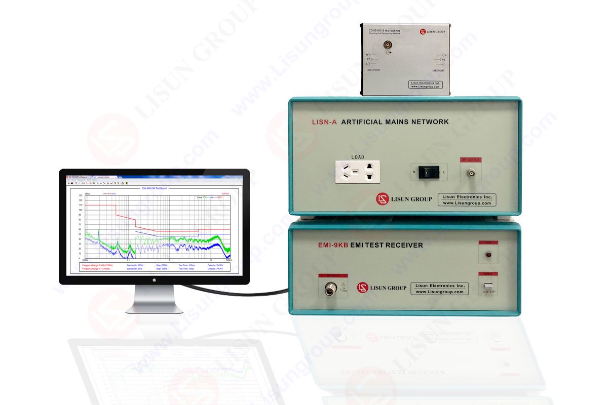
LISUN EMI-9KB EMI receiver has a full closure structure and high electro-conductivity material, resulting in a high shielding effect. The instrument self-EMI problem has been solved by new technology for EMI Test equipment. The test results are presented using the international test report format. The EMI-9KB is in full compliance with CISPR15:2018, CISPR16-1, GB17743, FCC, EN55015, and EN55022.
The LISUN EMI-9KB EMI Receiver operates on the frequencies of 9K-300MHz. It has 3pcs Isolation Transformers, CDNE-M316 Coupling/Decoupling Network for Emission, LISN-A Artificial Network Power (5A), Attenuator, and cables.
Every product on the market must comply with EMC regulations, which set upper limits for conducted and radiated emissions.
Conducted emissions are noise components produced by a device or sub circuit. They are conducted to another circuit via cabling, power/ground planes, PCB traces, or parasitic capacitance. The conducted emissions must be kept low. Otherwise, they will travel through the cables and cause problems for other devices.
Radiated emissions are the noise components produced by the entire system as an electromagnetic field. It allows the emissions to travel through the air and reach other devices.
Engineers understand that signal propagation through cables occurs without reflection (low frequency) can occur. This happens only when the cable length is smaller in length than the signal wavelength. In the case of a lumped model for the signal propagation medium, conducted emissions are considered an issue at low frequencies.
Signal propagation along the cable happens without reflection only if there is an impedance matching happening. If so, then the cable length that is significantly greater than the signal wavelength (high frequency) is provided along the signal path. The propagation of the signal through the conductors can be modeled as a distributed model (transmission line theory). Although in practice, systems frequently use conductors that are not designed as transmission lines for high frequencies. Such conductors can easily give off signals in the form of an electromagnetic field. They behave like an antenna rather than a transmission line. Therefore, radiated emissions are regarded as a problem at high frequencies.
EMC regulations are intended to measure the emissions produced by devices and their cables. The usual dimensions of devices and associated cables can go up to the length of 1.5m. Radiated emissions from them can occur only at frequencies greater than 30MHz. Here the dimensions of conductors that are part of the EUT can be slightly longer. Radiated emissions do not occur significantly at frequencies below 30MHz. It is recommended to evaluate the EUT only for conducted emissions.
The following is a typical setup for testing conducted emission from the EUT
• An EMI receiver or spectrum analyzer is required (suitable for pre-compliance)
• LISN (Line Impedance Stabilization Network)
• Ground Plane – The EUT, the LISN, and the receiver are all placed on the ground plane and connected to it.

Testing Conducted Emissions
A three-port device that is linked to the EUT, the receiver and the power supply is called LISN.
The LISNs provide standardized RF impedance across the EUT measurement point. The LISN connects the EUT’s measurement point to the receiver and virtually eliminates unwanted interference signals from the power supply. This prevents such signals from influencing test execution.
LISNs can be used to analyze DC, single-phase, or three-phase alternating current. The most common type is defined in CISPR 16-1-2. It has an equivalent impedance of 50 in parallel with 50uH + 5 across each line to earth for the EUT. It is called a “V-network” type for single-phase supply. This is because the stabilized impedance appears across each arm of the “V,” between line or neutral and earth connection.

Testing Conducted Emissions
The measured noise levels must be compared to the noise limits specified by EMC regulations. For the case of single-phase devices, noise measurements repetition frequency must be happening for each line (phase and neutral).
The ground plane plays an important role in standardizing the testing environment in the basic test setup. This is because parasitic parameters can influence a portion of the conducted noise, as explained further below.
The EMI receiver is a device designed specifically for EMI testing. It differs from a generic spectrum analyzer in several ways. It can be thought of as a spectrum analyzer with specific EMI testing features
• Scan parameters in accordance with global EMC regulations (for example, hold time, resolution bandwidth (RBW), detector, and so on).
•Automatic test execution with LISN control and switching between line phases in the event of an alternating current supply (single-phase or three-phase)
• A software interface for viewing scans, configuring them and saving test results

Electromagnetic disturbance that degrades the performance of electrical equipment or electronic device, works abnormally or fails. It can be divided into conducted interference test and radiated interference test. LISUN EMI-9KB is an automatic EMI receiver system for EMI (Electromagnetic Interference) radiation conduction or conducted emissions testing. It can do both conducted interference test and radiated interference test.
Lisun Instruments Limited was found by LISUN GROUP in 2003. LISUN quality system has been strictly certified by ISO9001:2015. As a CIE Membership, LISUN products are designed based on CIE, IEC and other international or national standards. All products passed CE certificate and authenticated by the third party lab.
Our main products are Goniophotometer, Integrating Sphere, Spectroradiometer, Surge Generator, ESD Simulator Guns, EMI Receiver, EMC Test Equipment, Electrical Safety Tester, Environmental Chamber, Temperature Chamber, Climate Chamber, Thermal Chamber, Salt Spray Test, Dust Test Chamber, Waterproof Test, RoHS Test (EDXRF), Glow Wire Test and Needle Flame Test.
Please feel free to contact us if you need any support.
Tech Dep: Service@Lisungroup.com, Cell/WhatsApp:+8615317907381
Sales Dep: Sales@Lisungroup.com, Cell/WhatsApp:+8618117273997

LISUN’s Motor-Operated Tool | Power Tool Testing solutions strictly comply with a range of core international standards, providing full support for safety and electromagnetic compatibility (EMC)...

LISUN’s transformer test solutions meet IEC 61558-1, IEC 60076-1, IEC 62041 standards. Covering safety, performance, EMC tests, ensuring transformers comply with global requirements.

LISUN’s household and appliance switch testing solutions meet IEC 60669, IEC 61058, IEC 62271 standards. Covering electrical, mechanical & EMC tests for global compliance.

For the CFL design and manufactory, LISUN can supply a full quality control test solution, including photometric, colorimetric, electricity, flicker, IES candela distribution, surge test, electrical...

 中文简体
中文简体