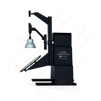
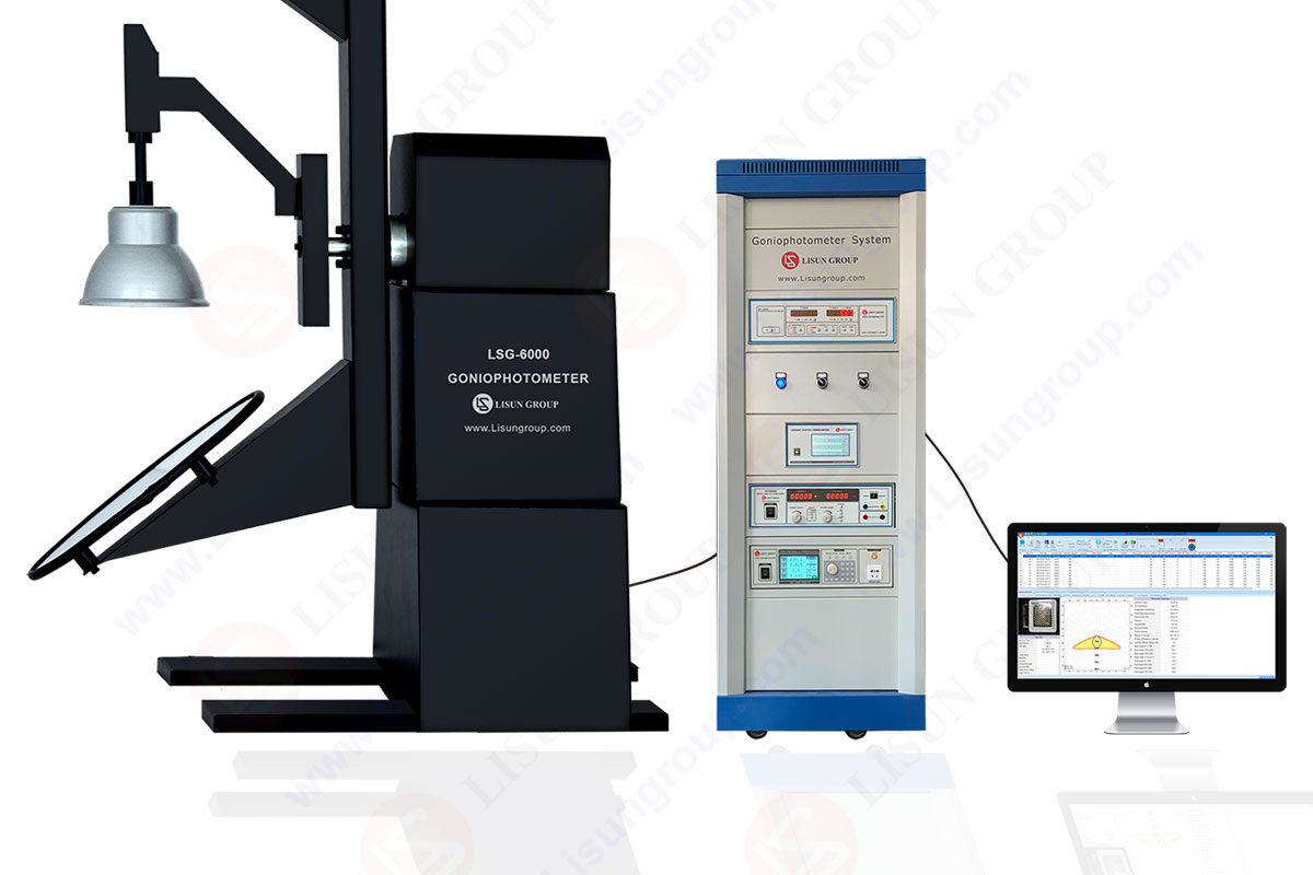
LM-79 Moving Detector Goniophotometer (Mirror Type C)
LSG-6000

High Precision Rotation Luminaire Goniophotometer
LSG-1890B

High Precision Rotation Luminaire Goniospectroradiometer
LSG-1890BCCD

Goniophotometer for Automotive and Signal Lamps
LSG-1950

Goniophotometer for Traffic Signal Lamps
LSG-1950S

Compact Goniophotometer
LSG-1200A

Near Field Moving Detector Goniophotometer
LSG-1900B
Select an organization
to browse standards
Goniophotometers are desktop systems used for measuring light intensity distribution, light flux, and color. This easy-to-operate system combines the functions of a goniophotometer for measuring the angle-dependent luminous intensity and spectroradiometer for generating colorimetric data required by standards. It comes in two types – horizontal and vertical – mainly used for testing the total luminous flux, light distribution curves, glare levels, and illuminance distribution maps for entire luminaires. Additionally, it enables to export IES or LDT files.
The LM-79 Goniophotometer working principle:
The Goniophotometer uses the photometry method. During testing, the sample luminaire or probe can be rotated to acquire parameters at different angles. Thus, the test result is a spatial light intensity table and spatial color table which displays the data from measurement taken at various directions instead of in just an average value. Plus, the distributed photometer is not affected by the luminaire’s housing or emission angles, since the light is directed straight into the detector, and both the luminaire or probe rotate for measuring different light intensity levels and color temperature levels. Of course, it will also provide average flux and color temperature information in its report.

Characteristics of Goniophotometers:
1. High Flexibility: Local and Far Field Angular Photometry Detectors System-Combined in One Instrument.
2. Fast Scanning: L Level Photometer Reduces The Measurement Time.
3. High Precision: Offering Up To 0.005 Degree of Angular Repeatability and High Grade (L) Photometer.
4. Intuitive Operation: Easy To Use. Measurement of Complex and Error-Prone Mirror-Angle Photometer has Become a Thing of the Past.
5. Variable Sizes: Detectors and Robot Sizes (Weight Capacity from 4 to 1000Kg) Can Be Provided; Special Models Can Be Provided As Well.
What is the Near-field Optical Distribution of a Light Source? How to Utilize the Source Near-field Angular Photometer to Achieve Near-Field Model? What Types of Files Can Be Generated with Source Near-Field Testing, and How to Make Use of these Generated Files?
1. The Model and Testing Principle of Near-Field Optical Distribution of Light Source
At present, two types of models are generally used in the optical design of LED, namely, “Source Far-Field Model” and “Source Near-Field Model”. Before understanding the Near-Field Model, let’s briefly introduce the familiar Source Far-Field Model.
The Source Far-Field Model views the light source as a point source, and all the light rays are emitted from the same point. Generally, the light emitted from the point source is isotropic. The Source Far-Field Model is obtained by the Far-Field Goniophotometer, which usually contains a mechanical structure (turntable) for supporting and positioning the test light source and a photodetector. According to CIE70 requirements, the distance between the light source and the detector should be sufficiently far (generally, the measurement distance should be 5 times the maximum emission surface of the LED light source) when the measurement is conducted. At this time, the light source can be regarded as a point source.
For LED light sources, especially white light sources, the brightness and color distribution on the surface are not homogeneous due to the influence of electrode design, chip structure and fluorescent powder coating method, as shown in Figure 1. The information obtained by the Far-Field Model for secondary optical design of LED light source is rougher, which can not accurately reflect the brightness and color space distribution differences of the LED light source surface, making it difficult to realize accurate secondary optical design for the light source. Therefore, it is critical to accurately measure the emission model of the light source for optical design and simulating results.
That is to say, the most essential difference between the Source Far-Field Model and the Source Near-Field Model is that the Source Far-Field Model views the light source as a point source, while the Source Near-Field Model views the light source as a complex surface source. The shape of the light source is represented by a plane, and all the light rays are emitted from the surface of the light source. The Near-Field Model is closer to the actual emission of LED light source. The measurement can obtain the brightness and color value of each point in the test plane, providing more accurate and detailed data for the optical design of LED light source.
The Near-Field Model of the light source can be obtained by the Near-Field Distribution Photometer, as shown in Figure a. The Near-Field Goniophotometer is composed of a Goniophotometer and an Imaging Photometer. The Imaging Photometer replaces the Photometer Detector in the Goniophotometer. The Imaging Photometer adopts a two-dimensional optical receiving element (such as CCD), which can measure the brightness value of each point in the measured plane with one sampling. The Imaging Photometer of the Near Field Goniophotometer faces the test LED light source and directly receives the beam of light from the LED light source. The beams emitted by the tested light source all have measurable brightness values that are independent of distance. By measuring the brightness values of each emitting point on the surface of the tested LED light source in all directions of the space, the illumination distribution of each plane of the LED light source, the spatial luminous intensity distribution and the total luminous flux of the LED light source can be accurately obtained by the method of light tracing, regardless of the testing distance, direction or surface curvature radius of the LED. If the colorimetric information is to be measured, the Imaging Photometer can be replaced by an Imaging Colorimeter to obtain the spatial chromaticity distribution of the LED light source.

a: Near Field Photometric Goniophotometer Structure Schematic
During the measurement, the light source can rotate around its own mechanical axis, and the Imaging Photometer / Colorimeter takes pictures of the light source from all angles of the space. The measured results at each designated angle contain both brightness and color information, constituting a three-dimensional spatial image of light output brightness and color. After the measurement, the measurement software will integrate these images into a Near-Field model to describe the brightness and color distribution of the light source, and give it in the form of luminous intensity. The luminous intensity I (x, y, z, θ, φ) is a function of position (x, y, z) and angle (θ, φ). If colorimetric and spectral measurements have been made, this function will also include chromaticity coordinates or spectra. The Near-Field Model of the light source can generate ray sets for optical design and extrapolation of the far-field distribution of the light source.
LSG-6000 Moving Detector Goniophotometer (Mirror Type C) was manufactured by LISUN completely meets LM-79-19, IES LM-80-08, COMMISSION DELEGATED REGULATION (EU) 2019/2015, CIE-121, CIE S025, SASO 2902, IS16106 and EN13032-1 clause 6.1.1.3 type 4 requirements. LSG-6000 is the latest upgraded product of LSG-5000 and LSG-3000 in compliance with the requirements of the LM-79-19 standard Clause 7.3.1, its an automatic light distribution intensity 3D curve testing system for measuring light. The darkroom can be designed according to the customer’s existing room size.

LM-79 Moving Detector Goniophotometer (Mirror Type C)
Lisun Instruments Limited was found by LISUN GROUP in 2003. LISUN quality system has been strictly certified by ISO9001:2015. As a CIE Membership, LISUN products are designed based on CIE, IEC and other international or national standards. All products passed CE certificate and authenticated by the third party lab.
Our main products are Goniophotometer, Integrating Sphere, Spectroradiometer, Surge Generator, ESD Simulator Guns, EMI Receiver, EMC Test Equipment, Electrical Safety Tester, Environmental Chamber, Temperature Chamber, Climate Chamber, Thermal Chamber, Salt Spray Test, Dust Test Chamber, Waterproof Test, RoHS Test (EDXRF), Glow Wire Test and Needle Flame Test.
Please feel free to contact us if you need any support.
Tech Dep: Service@Lisungroup.com, Cell/WhatsApp:+8615317907381
Sales Dep: Sales@Lisungroup.com, Cell/WhatsApp:+8618117273997
LISUN’s indoor and outdoor LED test solutions meet IEC 60598-1, IEC 62722-2-1, CIE 121 standards, covering safety, photometry, and environmental tests for global compliance.

 中文简体
中文简体