LM-79 Moving Detector Goniophotometer (Mirror Type C)
LSG-6000

High Precision Rotation Luminaire Goniophotometer
LSG-1890B

High Precision Rotation Luminaire Goniospectroradiometer
LSG-1890BCCD

Goniophotometer for Automotive and Signal Lamps
LSG-1950

Goniophotometer for Traffic Signal Lamps
LSG-1950S

Compact Goniophotometer
LSG-1200A

Near Field Moving Detector Goniophotometer
LSG-1900B
Select an organization
to browse standards
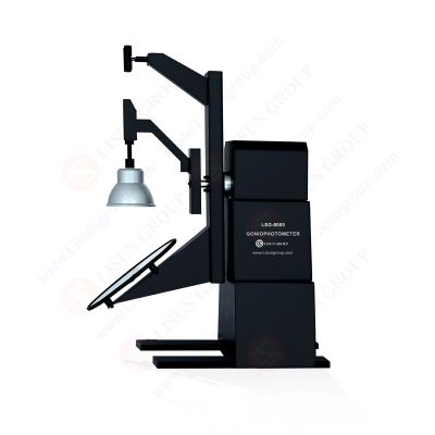
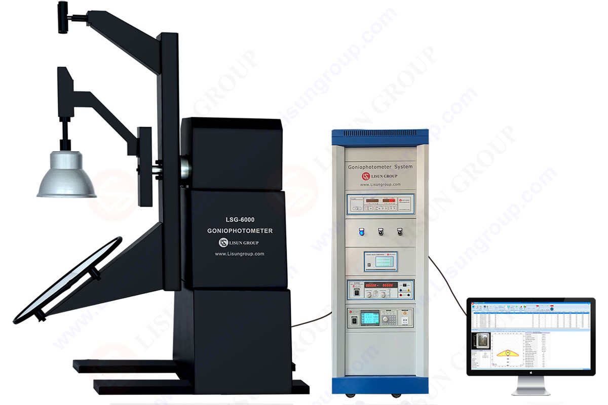
LSG-6000 goniophotometer is manufactured by LISUN. LISUN manufactures an LSG-6000 goniophotometer. It can measure all lighting sources, LED, Plant Lighting or HID luminaires such as indoor and outdoor luminaires, roadway luminaires, street lamps, floodlights, and other luminaries.

LM-79 Moving Detector Goniophotometer
There are six boxes in total. One package contains the base of the goniophotometer. The second includes the turntable of the goniophotometer. The third one consists of the clamps. A C-Gamma clamp, E27 holder, B-Beta clamp are present. The Fourth box contains the cabinet. The Fifth box includes the AC power source.
The Sixth box contains the DC power supply. All the other small devices and accessories are included in the box. Carefully open the box. Take out the bag and other accessories. A plastic bag is present in the package that contains a CD, calibrate certificates, and guarantee cards. There is software, user manual, operation video, and related standards in the CD.
• Open the back door of the cabinet. There is a wiring diagram on the door.
• Put the digital power meter rotary actuator, controller, DC power supply and AC power source into the correct positions of the cabinet.
• A power cord for the cabinet is present.
• Put the power cord through the hole. There is a fan on the top of the cabinet.
• Plug the power cords of the fan, digital power meter.
• Connect the four wires to the four terminals on the back of the power meter.
• Connect the communication cable to the communication box.
• Connect the output lines to the back of the DC power supply.
• Consider the positive and negative poles.
• Connect the communication cable to the communication box. Connect the output of the ac power source to the cabinet.
• Connect the communication cable to the communication box. Connect the communication box to the computer using the USB cable.
• There is a taper sleeve on the top of the base of the goniophotometer. The sleeve and the bottom are engraved with the same number.
• Make sure the numbers are in the same direction and fix the sleeve to the base using the screws.
• Open the dust cover of the turntable. There is a terminal bar under the dust cover.
• Lift the turntable using a forklift. There is also a terminal bar out of the taper sleeve.
• Please make sure they are in the same direction. Put the turntable down on the base slowly.
• Protect the terminal bar of the sleeve and make sure it goes through the hole successfully.
• Verify the direction of the turntable. Ensure that the six screw holes correspond to the base one by one.
• Fix the turntable on the base using our screws and gasket. Connect these two terminal bars.
• Put the dust cover to its original position. Move these four feet up, then move the goniophotometer to the correct place.
• Try to keep the side parallel to the wall. The side with the word faces the photodetector. There are four terminals marked with the numbers on the back of the cabinet.
• They are used to connect with the goniophotometer. These two terminals are connected to the power strip inside of the cabinet.
• It is used to power the darkroom equipment, including the goniophotometer.
• You can control the power supply of the entire system on the cabinet. Connect the grounding terminal to the ground.
• Assemble the photodetector and put it into the correct position.
• There is one to two communication cable for the goniophotometer.
• There are three wires connected to the photodetector. The signal line is from the goniophotometer. The communication cable is connected to the communication box inside the cabinet.
• A power adapter is present at the bottom of the goniophotometer.
• Turn on the system and make sure that all the devices in the system are turned on. Copy all the files on the CD to the computer. Double click to install the goniophotometer.
• Double click to install the driver for the communication box. Copy the APK file to your ANDROID phone and install it. Turn on the Bluetooth of your phone. Open the application on your phone and connect the goniophotometer.
• The application is used to run the goniophotometer. But, it can not run the measurement
• Photometric Data
• Luminous Intensity Distribution
• Zonal Luminous Flux
• Luminaries Efficiency
• Distribution
• Coefficient Of Utilization
• Luminance Limitation Curves Glare
• Maximum Ratio of Distance to Height
• Equal Illuminance Diagrams
• Curves of Luminaires VS Lighting Area
• Isocandela Diagrams
• Efficient Luminescence Angle
• EEI, UGR, etc.
• The near field detector moves together with the big mirror in a line. The big mirror and the far-field sensor move synchronously.
• The burning position of the luminaries will be kept without moving at all. The detector will always sense the light directly from the luminaries.
• The rotary motor is from Japan MITSUBISHI MOTORS, and the angle decode system is from Germany.
• The rotary engine helps the goniophotometer to rotate smoothly with high accuracy. It is very stable when we start and stop the motor.
• The working principles are as per the instructions of the IESNA and CIE. The LSG-6000 meets the LM-80, LM-79, LM-75, GB, EN and CIE 121-1996 standards.
• A particular collimation device with a cross laser line helps you install the position of the luminaires under test conveniently and accurately.
• The luminaire under test rotates around the mirror with an angle of (γ) vertical axis ±180° (or 0-360°) and the luminaire rotates around itself with an angle of (C) horizontal axis ±180° (or 0-360° ).
• The accuracy of angle: 0.05°, Resolution of angle: 0.001°
• Accuracy of Goniophotometer detector: Constant temperature DIN 5032-6/CIE pub1. No. 69 Class L
• LISUN goniophotometer software can export CIE, IES, LDT and other format files. These format files can be used via other illumination and luminaire design software such as DiaLux.
• Connect the goniophotometer to the PC via a USB cable. English version software can run on Win7, Win8 or Win10, Win11
• LSG-6000 can be used together with a CCD Spectroradiometer to test spatial CCT Distribution and other Spectral color parameters. We call this system “Gonio Spectroradiometer (LSG-6000CCD)”. LSG-6000CCD Gonio Spectroradiometer
• The LSG-6000CCD software and hardware support the plant lighting PAR, PPF and PPFD spatial distribution test, and it can export IES/LDT files

Goniophotometer works according to the measuring principle of the fixed detector and rotating lamp method. We install the measuring lamp on a two-dimensional rotating worktable. The luminous center of the light coincides with the rotating work table’s turning center through the laser beam of the laser sight.
Lisun Instruments Limited was found by LISUN GROUP in 2003. LISUN quality system has been strictly certified by ISO9001:2015. As a CIE Membership, LISUN products are designed based on CIE, IEC and other international or national standards. All products passed CE certificate and authenticated by the third party lab.
Our main products are Goniophotometer, Integrating Sphere, Spectroradiometer, Surge Generator, ESD Simulator Guns, EMI Receiver, EMC Test Equipment, Electrical Safety Tester, Environmental Chamber, Temperature Chamber, Climate Chamber, Thermal Chamber, Salt Spray Test, Dust Test Chamber, Waterproof Test, RoHS Test (EDXRF), Glow Wire Test and Needle Flame Test.
Please feel free to contact us if you need any support.
Tech Dep: Service@Lisungroup.com, Cell/WhatsApp:+8615317907381
Sales Dep: Sales@Lisungroup.com, Cell/WhatsApp:+8618117273997
LISUN’s indoor and outdoor LED test solutions meet IEC 60598-1, IEC 62722-2-1, CIE 121 standards, covering safety, photometry, and environmental tests for global compliance.

 中文简体
中文简体