LM-79 Moving Detector Goniophotometer (Mirror Type C)
LSG-6000

High Precision Rotation Luminaire Goniophotometer
LSG-1890B

High Precision Rotation Luminaire Goniospectroradiometer
LSG-1890BCCD

Goniophotometer for Automotive and Signal Lamps
LSG-1950

Goniophotometer for Traffic Signal Lamps
LSG-1950S

Compact Goniophotometer
LSG-1200A

Near Field Moving Detector Goniophotometer
LSG-1900B
Select an organization
to browse standards
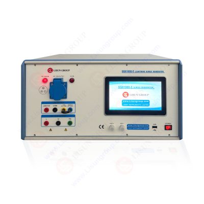
Surge generator anti-interference measurement is based on the international standard IEC 61000-4-5.

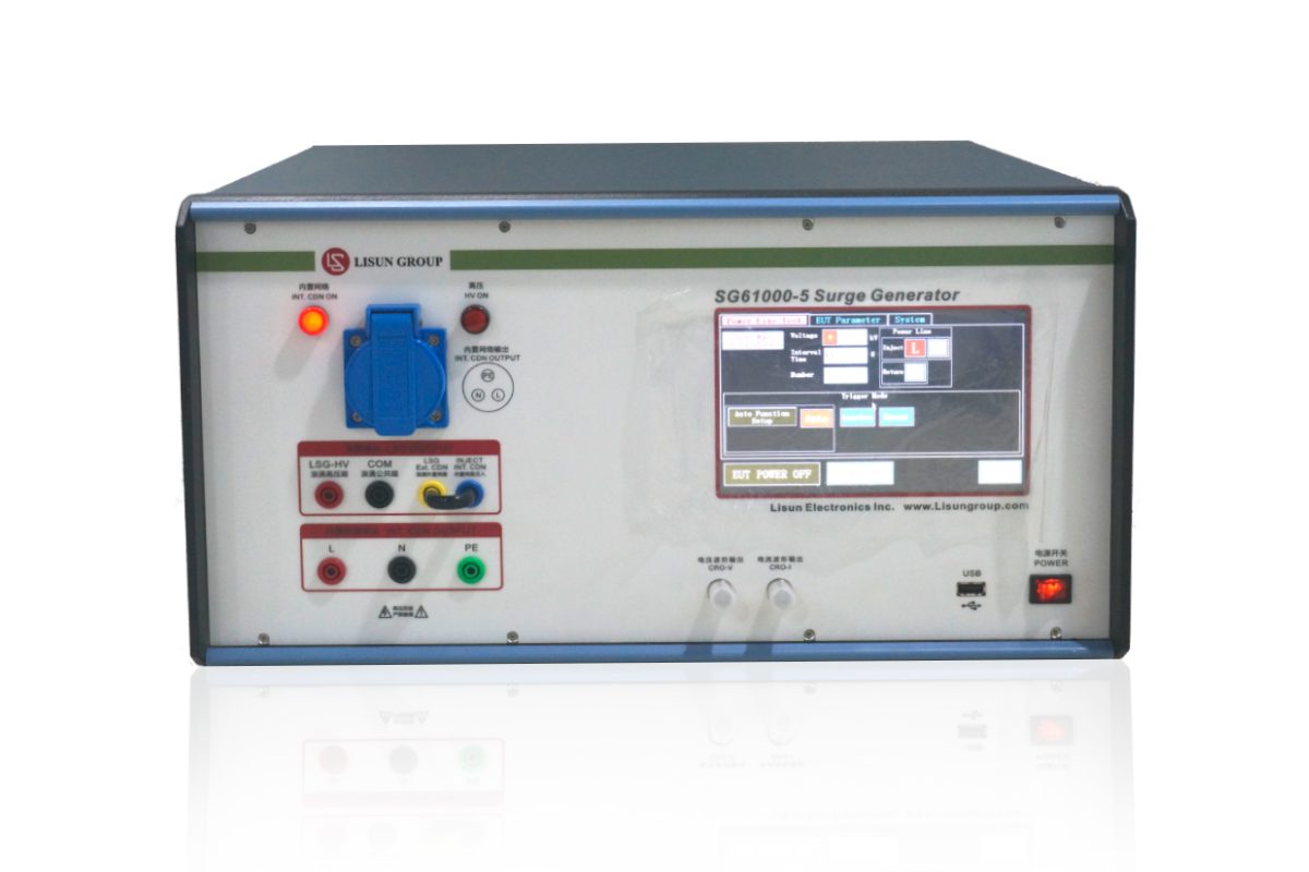
SG61000-5_Surge Generator
1 Test objective
The entire lightning stroke in the nature (namely the indirect thunder such as the lighting stroke between the clouds, or the lighting stroke happened to the adjacent objects) can induce the surge voltage and current in outdoor aerial. Besides, huge surge voltage and current will also be induced in the supply circuit of the instant switch in the power station or switching station. The common characteristics of the two kinds of surge include high energy (compared with the energy, the static electricity is P joule level, pulse group is the millijoule level, lightning surge is hundreds of the joule level, which is one million times of the former two interfering energy), slow waveform (microsecond level, but the static electricity and pulse group are nanosecond level, even the sub nanosecond level), and low recurrence frequency.
IEC 61000-4-5 is a standard that provides an objective evaluation on the resistance to surge interference ability for the electrical and electronic equipment through the experiment of simulating lighting surge.
2 Surge generators
This standard has mentioned two kinds of surge generators, which respectively simulate the situation of the power line and the communication line. The waveforms of the two kinds of surge are different because of the different line impedance.
(1)Comprehensive wave generator used for the power lines test
“Comprehensive wave” refers to the waveform parameters formed by the voltage wave and the current wave regulated by the standard in a surge generator circuit(when the output terminal of the generator is open circuit, it will form the voltage surge wave; when the output terminal of the generator is short circuit, and it will form the current surge wave). The requirement of the generator line and the waveform is shown as the following figures:

IEC 61000-4-5: Surge Test and Measurement Techniques
U: High-voltage power supply
Rs: Pulse duration forming resistor
Rc: Charging resistor
Rm: Impedance matching resistor
Cc: Reservoir capacitance
L: Rising time forming resistor

IEC 61000-4-5: Surge Test and Measurement Techniques
Front wave time: T1=1.67XT=1.2μs±30%
Half peak value time: T2=50μs±20%
1.2/50μs Open-circuit voltage waveform (based on IEC 60-1 waveform regulation)

IEC 61000-4-5: Surge Test and Measurement Techniques
Front wave time: T1=1.25XT=8μs±30%
Half peak value time: T2=20μs±20%
8/20μs Open-circuit voltage waveform (based on IEC 60-1 waveform regulation)
The basic requirement of the comprehensive generator:
Open-circuit output voltage (±10%): 0.5kVP to 4kVP
Short-circuit output current (±10%): 0.25kAP to 2kAP
Generator resistance: 2Ω (it is the key to connect the open-circuit voltage wave and the short-circuit current wave)
Additional resistance: 10Ω or 40Ω, form 12Ω or 42Ω internal resistance
Surge output polarity: positive / negative
Surge phase shifting range:0°~360° (surge output synchronizes with the power supply)
Maximum repetition frequency: at least once per minute
(2)10/700μs surge wave generator used for telecommunication line
The generator line and the waveform are shown as the following figure:

IEC 61000-4-5: Surge Test and Measurement Techniques
U: High-voltage power supply
Rs: Pulse duration forming resistor
Rc: Charging resistor
Cc: Reservoir capacitance (20μF)
Rm: Impedance matching resistor (Rm1=15Ω, Rm2=25Ω)
Cs: Rising time forming resistor (0.2μF)

IEC 61000-4-5: Surge Test and Measurement Techniques
3 Test methods
Since the voltage and the current of the surge test are relatively slow, the configuration of the lab is rather simple. The power circuit test is finished through coupling decoupling network. The following figure is the single-phase test circuit diagram which has the requirement of the differential mode and common mode test.

IEC 61000-4-5: Surge Test and Measurement Techniques
4 Attention in the test
(1)Protective measures must be taken in accordance with the requirement of the manufacturer before the test.
(2) The test rate is once per minute. It should not be too quick so as to form a recovery process for protecting the machine’s performance. As a matter of fact, it is impossible for the natural lighting phenomenon and the large switch of the transformer substation to have very high repetition rate. In general, there are five -times test for each positive and negative polarity.
(3) The voltage should be gradually tested from low level to high level to avoid the false scent of the sample I-V nonlinear characteristics. In addition, the test voltage should be confirmed not to exceed the requirement of the product standard in order to avoid the unnecessary damage.
5 Severe degree of the test
The severe degree of the test can be divided into 1, 2, 3, and 4 and X level. Level 13 parameter of the power circuit differential mode is not given, the other levels are respectively 0.5kV、1kV、2kV and undetermined. Each level parameter of the power circuit common mode test is 0.5kV、1kV、2kV、4kV and undetermined.
The severe degree of the test depends on the environment (the environment that may suffer the surge) and the installation condition; it is mainly divided into the following types:
Level 1: Better protective environment, such as the control room of the factories or the power station.
Level 2: Certain protective environment such as factories with no strong interference.
Level 3: Common electromagnetic harassment environment without specified installation requirement for the equipment such as the cable network of common installation, industrial work place and power substation.
Level 4: Severe harassment environment such as civil aerial, high-pressure power substation without protection.
Level X: Special level should be confirmed after the consultation of the user and the manufacturer.Selection of the product level depends on the product standard.
6 Comment on the standards
At present, there are many standards mentioning the situation of using 1.2/50μs lighting to do the test, but the different standard has different test objective. For example, high-pressure test also mentioned the lighting test for the impulse withstand voltage test with the high-pressure and high-resistance generator. At this moment, although the voltage of the generator is high, the energy is not huge. This kind of test is conducted in the off-line state of the equipment. On the contrary, IEC 61000-4-5 standard requires conducting the surge anti-interference measurement. Due to the low circuit impedance, the output impedance of the generator is also required to be low. In this way, the generator suitable for surge anti-interference measurement not only needs to have high output voltage, but also needs to have low output impedance and large energy output characteristics. Since the equipment conducts the measurement in the on-line state, coupling and decoupling network should be used. It can be seen that the above mentioned two kinds of experiments are totally different, which should not be confused.
Lisun Instruments Limited was found by LISUN GROUP in 2003.LISUN quality system has been strictly certified by ISO9001:2015. As a CIE Membership, LISUN products are designed based on CIE, IEC and other international or national standards. All products passed CE certificate and authenticated by the third party lab.
Our main products are Goniophotometer, Surge Generator, EMC Test Systems, ESD Simulator, EMI Test Receiver, Electrical Safety Tester, Integrating Sphere, Temperature Chamber, Salt Spray Test, Environmental Test Chamber, LED Test Instruments, CFL Test Instruments, Spectroradiometer, Waterproof Test Equipment, Plug and Switch Testing, AC and DC Power Supply.
Please feel free to contact us if you need any support.
Tech Dep: Service@Lisungroup.com, Cell/WhatsApp:+8615317907381
Sales Dep: Sales@Lisungroup.com, Cell/WhatsApp:+8618917996096

LISUN’s LM-79 and LM-80 test solutions cover LED photometric, colorimetric, and lumen maintenance tests, meeting IES standards for accurate performance evaluation.
LISUN’s indoor and outdoor LED test solutions meet IEC 60598-1, IEC 62722-2-1, CIE 121 standards, covering safety, photometry, and environmental tests for global compliance.

LISUN’s Motor-Operated Tool | Power Tool Testing solutions strictly comply with a range of core international standards, providing full support for safety and electromagnetic compatibility (EMC)...

LISUN’s electric toy testing solutions cover IEC 62115, EN 71-1, ASTM F963 standards. Including electrical, mechanical, flammability tests to ensure toy safety compliance globally.

LISUN’s transformer test solutions meet IEC 61558-1, IEC 60076-1, IEC 62041 standards. Covering safety, performance, EMC tests, ensuring transformers comply with global requirements.

LISUN’s energy meter testing solutions align with IEC 62052-11, IEC 62053 series standards. Covering safety, electrical, environmental, and EMC tests, we help manufacturers meet global compliance...

LISUN’s household and appliance switch testing solutions meet IEC 60669, IEC 61058, IEC 62271 standards. Covering electrical, mechanical & EMC tests for global compliance.
LISUN’s cable and wire test solutions meet IEC 60245-1, IEC 60227-1, IEC 60502-1 and IEC 60189 standards, covering electrical, mechanical, and safety tests for global compliance.
LISUN has all equipment according to the IEC60669 measurement, including environmental chamber, IP code waterproof dustproof test, switch lift test, etc.

Lisun can supply full test solutions for fluorescent lamp, including integrating sphere system, goniophotometer system, EMI EMC test, electronic ballast tester, electrical safety test, etc.

For the CFL design and manufactory, LISUN can supply a full quality control test solution, including photometric, colorimetric, electricity, flicker, IES candela distribution, surge test, electrical...

LISUN’s LED driver test solutions cover lab testing, online testing, EMC/EMI tests, and safety checks, meeting IEC 60335, UL 60335 standards for reliable performance evaluation.

 中文简体
中文简体