LM-79 Moving Detector Goniophotometer (Mirror Type C)
LSG-6000

High Precision Rotation Luminaire Goniophotometer
LSG-1890B

High Precision Rotation Luminaire Goniospectroradiometer
LSG-1890BCCD

Goniophotometer for Automotive and Signal Lamps
LSG-1950

Goniophotometer for Traffic Signal Lamps
LSG-1950S

Compact Goniophotometer
LSG-1200A

Near Field Moving Detector Goniophotometer
LSG-1900B
Select an organization
to browse standards
Goniophotometer is a device that serves many purposes to test products that utilize light energy. This device can be used to get photometric values and led intensity measurements from appliances and electronics. In this article, we will see the types of goniophotometer and their use to get led intensity measurements.
A goniophotometer is a device that measures the parameters of directional light distribution in lamps and luminaires. It gathers photometric information from a variety of spherical places. It encircles the item under test with a web of photometric data. Various equipment are used to collect gonio photometric data, which is then given in a number of angular coordinate systems.

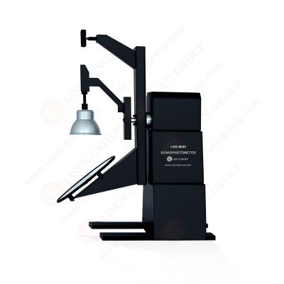
LM-79 Moving Detector Goniophotometer LSG-6000
The angular or spatial distribution of light from a light source is measured using gonio photometry. A laser is a high-powered light source. Typically, the beam is tiny and travels in a near-perfect straight line. This renders a laser inefficient for everyday use. A perfect isotropic radiator is an incandescent lamp. In all directions, it produces identical intensity.
The goal of photometry is to measure light while considering the sensitivity of the human visual system. Photometry only detects light in the visible spectral range of 360 nm to 830 nm, which is sensitive to human eyes.
While radiometry detects light in all spectral regions, including ultraviolet and infrared, photometry exclusively measures light in the visible spectral band, which spans 360 nm to 830 nm and is sensitive to human eyes. As a result, photometry is critical for evaluating light sources and objects that are used for lighting, signaling, displays, and other applications where light is intended to be viewed by humans.
The LSG-6000 Moving Detector Goniophotometer (Mirror Type C) complies fully with the specifications of LM-79-19, IES LM-80-08, COMMISSION DELEGATED REGULATION (EU) 2019/2015, CIE-121, CIE S025, SASO 2902, IS16106, and EN13032-1 clause 6.1.1.3 type 4 and EN13032-1 clause 6.1.1.3 type 4. According to the LM-79-19 standard, the LSG-6000 is the most recent version of the LSG-5000 and LSG-3000.
LM-75-01 was issued by the Illuminating Engineering Society of North America (IESNA) in 2001. It has since been updated in 2019 to LM-75-19. It gave three usual types of goniometer motion. A, B, and C are the three types that define the motion.
Type A and B goniophotometers move in a comparable way. In both situations, the device under test was rotated 90 degrees around orthogonal horizontal and vertical axes. The horizontal-vertical coordinate system corresponds to the type A or B coordinate system (H-V or X-Y).
The device under test is rotated about an azimuthal axis (the nadir angle, which is normally aligned along the polar axis of the coordinate system), while the elevation (or inclination) axis is the other axis of motion in a type C goniophotometer. – is the abbreviation for the type C spherical coordinate system, with (theta) representing the elevation axis and (psi) representing the azimuthal axis.
Lamps and architectural lighting products are commonly measured with Type C goniophotometers. Type C goniophotometers with an accessory kit that can be converted to type B motion have been designed by several manufacturers (and vice versa).
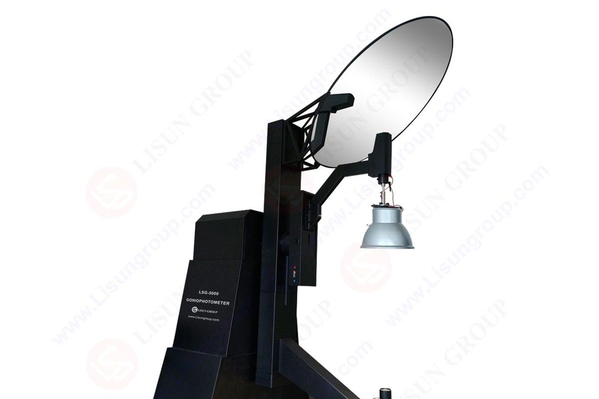
Because of this versatility, a single goniophotometer can be used with any light source. These include architectural luminaires and directing vehicle lights. Type C motion is used in goniophotometers with moving detectors or moving mirrors. The device under test is held vertically and shines down or up in this method.
The stability of the tested bulbs, the measurement distance, angle, and brightness are the four critical criteria for evaluating the luminous intensity distribution. It is vital to always maintain the test light source in a steady state. Between the tested luminaries and the photometer, exact distance, brightness, and relative rotation angle measurements are possible.
The huge mirror and the near field detector move in a straight line. Both the far-field detector and the large mirror move at the same time. The luminaires’ burning positions will be maintained without movement. Light from the luminaires will always be detected by the detector.

LSG-6000 Moving Detector Goniophotometer Working Principle
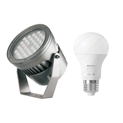
A regular photometric bench and standard photometers can be used to measure the luminous intensity (unit: candela) of LEDs in a far field condition, at a distance far enough away from the test LED to be considered a point source (typically 2 m or longer). However, in the LED sector, it is standard practice to measure LEDs at shorter distances, such as 10 cm to 50 cm. The custom is thought to have originated when LEDs were dim, and photometers were not extremely sensitive.
Even though LEDs are brighter, this behavior persists. Because many LEDs include epoxy lenses, they do not act like a point source, thus the inverse-square law does not hold well when measuring luminous intensity at short distances. The effective center of LED emission might move away from the LED’s physical center. When measured at different distances, this produces differences in measured luminous intensity, especially when the distance is small. One of the major sources of light intensity measurement variation was discovered to be this.
To address this issue, the Commission International de l’Eclairage (CIE) issued CIE 127 (1997) and CIE 127:2007, which regulated the measurement distances for LED intensity measurements (100 mm and 316 mm). The photometer aperture should be round with an area of one cm2. The distance should be measured from the tip of the LED encapsulation. The measuring direction should match with the mechanical axis of the LED.
Because the value can deviate somewhat from the LED’s true (far-field) luminous intensity, the luminous intensity measured under these standardized settings is referred to as the CIE Averaged LED Intensity. The two distances are distinguished by Conditions A and B for 316 mm and 100 mm, respectively. The CIE recommendation for determining the intensity of individual LEDs should be followed. This recommendation does not apply to LED clusters, arrays, or fixtures made of LEDs. When comparing test LEDs to calibrated standard LEDs or a calibrated standard photometer head, spectral mismatch compensation is done as appropriate.
LISUN Instruments Limited was found by LISUN GROUP in 2003. LISUN quality system has been strictly certified by ISO9001:2015. As a CIE Membership, LISUN products are designed based on CIE, IEC and other international or national standards. All products passed CE certificate and authenticated by the third party lab.
Our main products are Goniophotometer , Integrating Spheres , Spectroradiometer , Surge Generator , ESD Simulator Guns , EMI Receiver , EMC Test Equipment , Electrical Safety Tester , Environmental Chamber , Temperature Chamber , Climate Chamber , Thermal Chamber , Salt Spray Test , Dust Test Chamber , Waterproof Test , RoHS Test (EDXRF) , Glow Wire Test and Needle Flame Test .
Please feel free to contact us if you need any support.
Tech Dep: Service@Lisungroup.com , Cell/WhatsApp:+8615317907381
Sales Dep: Sales@Lisungroup.com , Cell/WhatsApp:+8618117273997
LISUN’s indoor and outdoor LED test solutions meet IEC 60598-1, IEC 62722-2-1, CIE 121 standards, covering safety, photometry, and environmental tests for global compliance.

 中文简体
中文简体