LM-79 Moving Detector Goniophotometer (Mirror Type C)
LSG-6000

High Precision Rotation Luminaire Goniophotometer
LSG-1890B

High Precision Rotation Luminaire Goniospectroradiometer
LSG-1890BCCD

Goniophotometer for Automotive and Signal Lamps
LSG-1950

Goniophotometer for Traffic Signal Lamps
LSG-1950S

Compact Goniophotometer
LSG-1200A

Near Field Moving Detector Goniophotometer
LSG-1900B
Select an organization
to browse standards
An immunity test called EFT Immunity Measurement (EFT61000-4) is used to evaluate how well electrical and electronic equipment performs when subjected to interference. A device is put through a number of tests to see if it can withstand fast transients like electrostatic discharge and power line transients.
Verifying the laboratory’s operating parameters, examining the EFT waveform, running the test, assessing the results, and creating the test report are all steps in the testing process. The IEC 61000-4-4 EFT immunity tester was specifically created to meet the needs and features of EFT measurement, and it is the optimum source of disruption for EMS measurements.
It performs admirably, offering features like high stability, high reliability, simplicity of use, etc. It complies with IEC 61000-4-4, EN 61000-4-4, GB/T17215.301, GB/T17215.322, and GB/T17626.4 standards. LCD touch screen with both English and Chinese on EFT61000-4. This paper will discuss in detail what Immunity test measurement is basically and will then move on to describe LISUN’s EFT Immunity Measurement |EFT61000-4|. It also incorporates product detail, the procedure of the testing and its importance.
What is Immunity Testing
EFTs are typically high-frequency pulses produced by sparking and are frequently observed in electrical systems and equipment. These sparks, also known as arcing, happen when lines touch, when a circuit is connected to or disconnected from a power source, or when switchgear is in use.
When inductive loads like relays or motors are de-energized, EFTs, also known as burst events, occur in power distribution lines; power factor correction equipment is a source of EFTs. Ethernets, data cables, and electric car systems are other technologies that have EFT problems.
EFTs should be kept to a minimum in electrical systems, and equipment must be able to withstand them up to a certain point without malfunctioning. Due to the fact that it establishes dependability, upholds quality, and assures compliance with industry standards, EFT testing is essential to the sector.
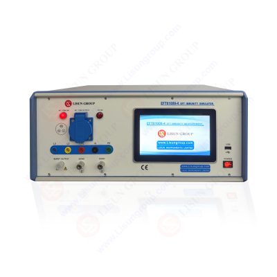
EFT Immunity Measurement |EFT61000-4 |
The EFT61000-4EFT immunity test was specifically created to meet the needs and features of EFT measurement, and it is the optimum source of disruption for EMS measurements. It performs admirably, offering features like high stability, high reliability, simplicity of use, etc. It complies with IEC 61000-4-4, EN 61000-4-4, GB/T17215.301, GB/T17215.322, and GB/T17626.4 standards. English and Chinese LCD touch screens are available on the EFT61000-4.
EFT testing is a method for determining how immune electrical and electronic equipment is to interference. A device is put through a number of tests to see if it can withstand fast transients like electrostatic discharge and power line transients. Verifying the laboratory’s operational conditions, confirming the EFT waveform, running the test, evaluating the results, and test report preparation.
EFT testing is possible on signal, earth, and control ports as well as AC and DC power supply lines. EFTs or bursts of high-frequency pulses with delays are introduced into the system during this form of testing. Whether or not the normal recommendations are followed will determine how long, how often, and how soon the bursts occur.

EFT61000-4_EFT Immunity Measurement
In a variety of EFT testing techniques, EFTs are delivered at specific injection locations. One example is the application of the EFT through a capacitive coupling clamp in signal/control ports with wire lengths of less than 3 m. The most popular technique involves using AC power cables to apply EFT; EFT pulses are then sent to both the line and neutral lines. A typical EFT test setup includes the following:
• ground reference plane (GRP)
• coupling network,
• decoupling network,
• test generator
• equipment under test (EUT)
A coupling and decoupling network is necessary in the test setup to test AC or DC supply ports. A capacitive coupling clamp is used for signal, data, control, or I/O ports. With no galvanic connection to the terminals or shielding of the EUT components, a coupling clamp facilitates quick coupling of EFTs to the EUT. The protective earth is connected to the GRP in the test setup. It is essential to verify that the voltage difference between the protected earth and the test generator’s neutral is less than 1 V before moving on to the EFT testing. The EUT should stand alone and mounting it on insulating support is standard procedure.
The GRP should stretch at least 100 mm in all directions from the EUT positioned on it. Additionally, the earth connections are established, and a test generator is installed on the GRP. In EFT testing of electronic devices, only the EUT is permitted as an earthing connection. A 500mm gap must separate the EUT from other conductive components. The length of all cables in the test setup must be kept at 500mm with a tolerance of 50mm, and they must all be in insulation supports. If the length is greater, this is accomplished by folding the cables into the shape of a “8.”
Product detail and specifications
Certain product specifications of LISUN’s EFT Immunity Measurement equipment include:
• Pulse frequency: 1 kHz-1000 kHz; output voltage: 0-5000V (Adjustable)
• Positive, Negative, or Automatic Positive/Negative Polarity
• Source impedance: 50% to 20% and 1000 to 20%
• A pulse’s rise time is 5 nanoseconds plus 30%
• Pulse width at 50 ns: 50 ns30%
• Testing features: Choose a free-form test mode or an IEC level
• Pulse width at 1k: 35ns to 150ns
• Burst duration: 0.01ms to 20ms
• Burst period: 100ms to 500ms
• Test time: 1s to 9999s
• Working Power: AC220V (Option 110V) 10%, 50/60Hz
• Coupling/Decoupling Network: Built-in 20A with 3 phases and 5 wires
Choose the LISUN EFT-CLAMP Capacitive Coupling Clamp for testing a communication line such as an RJ45 cable. Additionally, it is advised that clients use the EFT-DESK in conjunction with the EFT61000-4 EFT immunity tester.
Procedure
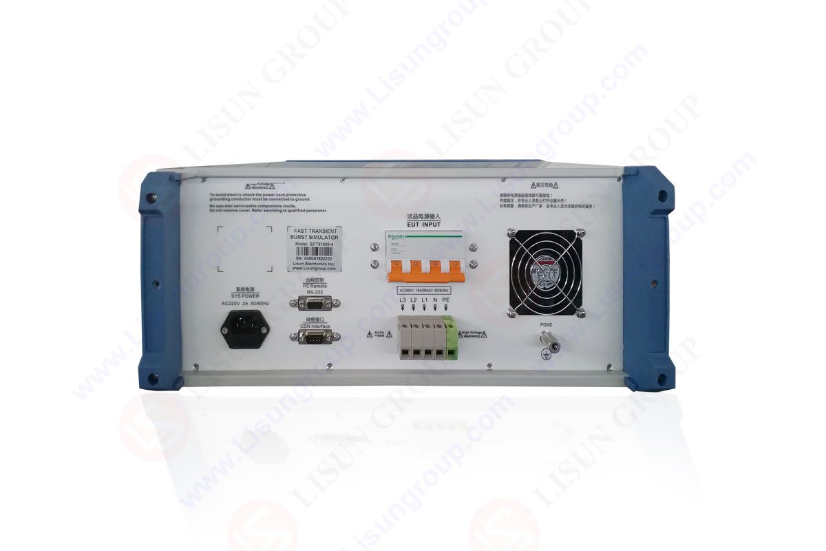
There are L1, L2, L3, N, and PE interfaces for performing the IEC 61000-4-4 EFT immunity test. Earth and PE are two distinct ideas. In the experimental setup figure of the standard, we can see that electrical fast pulse interference is a common mode. The signal cable from the test generator can connect with the corresponding power lines (L1, L2, L3, N, and PE) through the selectable coupling capacitor, and the shield of the signal cable connects with the coupling/decoupling network chassis, which is connected to the reference ground terminal.
As a result, the interference added to the power line is common mode interference, and for the experimental method using a coupled folder, the electrical fast pulse will be added into the tested cable through the distributed capacitance that is between the coupling plate and tested cable. This shows that burst interference is actually applied between the power line and the reference earth. However, the tested cable still got a pulse that was approximate to the reference ground plane.
As a result, the interference caused by the coupling clamp on the tested cable is still common mode. We can take the necessary steps to ensure that the equipment passes the test once the type of interference has been determined. As a result, it is clear that the power filters’ X capacitor (differential mode capacitor) cannot stop EFT interference. The common mode capacitance, or Y capacitors, will function if the device has a metal shell. We can avoid entering the circuit by avoiding the high-frequency EFT to the device shell and then returning via the dispersed capacitance between the device shell and the reference ground.
Equipment failure is caused by electrical fast pulse interference. According to research conducted by international academics, a single pulse’s energy is negligible and won’t result in equipment malfunction. However, when the aforementioned energy has collected to a certain point, the interference signal of burst charges apparatus line connection capacitance has the potential to result in power line malfunction (as well as the system).
As a result, the line error will have a time process and some chance (cannot guarantee the time interval of the error, especially when the tested voltage reaches the critical point). Furthermore, it is challenging to determine whether applying a pulse group simultaneously or separately may cause the device to malfunction more frequently. Furthermore, it is difficult to determine if the instrument is more sensitive to positive or negative pulses.
Practice has shown that for a specific measured voltage, one gadget is typically very sensitive to the polarity of a power cord. According to experiments, the power line is far less vulnerable to electrical fast pulse interference than the signal line. Effective solutions for ensuring that equipment passes electrical fast pulse testing. We first examine the interference injection techniques: By linking the 33nF capacitance of the decoupling network, the EFT interference signal is coupled to the main power lines. The cutoff frequency for 33nF capacitance is 100K.
The cut-off frequency for 100pF capacitance is 30MHz, allowing interference signals with frequencies greater than 30MHz to pass but not those with frequencies higher than 100KHz. Electrical fast pulses have interference waveforms of 5ns/50ns, 5k repetition frequency, 15ms pulse length, and 300ms burst repetition time. The pulse repetition frequency determines how far apart each discrete spectral line is in the spectrum, which the Fourier transform describes as having 5K to 100M spectral lines.

EFT61000 4 EFT Immunity Measurement
As a result of the foregoing, we can conclude that the coupling capacitance that applies the interference serves as a high-pass filter. Because the capacitance’s impedance decreases as frequency increases, the interference’s low-frequency components won’t be coupled to the EUT; instead, only the interference signal’s higher frequencies will do so. Because the impedance of the capacitance increases with frequency, adding the common mode inductance to the EUT circuit will attenuate some of the high-frequency interference. However, it is important to note that it must be added to both the main power line and its return line to prevent saturation and defeat the purpose of attenuating interference.
Importance
In today’s technology-driven society, lasers or LEDs are used in numerous items, whether they are industrial tools, medical devices, or lab equipment. Safety from the laser and LED radiation is a major worry for customers. We provide a range of laser and LED-related services, from testing to thorough analyses to getting your items a laser or LED UL Verified Mark.
Additionally, products can be evaluated by our cutting-edge labs around the globe to show whether they adhere to the necessary radiation safety regulations. Simple optical output measurement findings to IECEE CB Scheme Test Reports and Certificates-our team of professionals can produce a wide range of deliverables.
FAQs
How pre-compliance testing is set up for EMI receiver and EMC tests?
EMC testing is required to obtain an Electromagnetic Emission and Immunity test certification before a product is released onto the market. Real EMC testing, however, are expensive to do. Before going through the actual EMC test, the product must first undergo testing at an EMC pre-compliance test lab. Pre-compliance testing will mimic each test performed at EMI/EMC test facilities to ensure that the device will pass the EMI/EMC compliance test. Pre-compliance testing is less expensive and will yield results that are very similar to those of expensive and difficult-to-pass compliance test labs.
What purpose does the LISUN EFT Immunity Measurement (EFT61000-4) gadget serve primarily?
The objective of IEC/EN 62471 is to assess the risks from optical radiation posed by various lights and lamp systems. Additionally, it is utilized to replace the IEC/EN60825 standards for the requirements of the energy level of LED products. The demands of optical biology, such as those related to radiation intensity and radiant brightness, grew as a result. According to test results on the product, this standard classifies hazards into four categories: low damage, medium hazard, and high hazard.
Lisun Instruments Limited was found by LISUN GROUP in 2003. LISUN quality system has been strictly certified by ISO9001:2015. As a CIE Membership, LISUN products are designed based on CIE, IEC and other international or national standards. All products passed CE certificate and authenticated by the third party lab.
Our main products are Goniophotometer, Integrating Sphere, Spectroradiometer, Surge Generator, ESD Simulator Guns, EMI Receiver, EMC Test Equipment, Electrical Safety Tester, Environmental Chamber, Temperature Chamber, Climate Chamber, Thermal Chamber, Salt Spray Test, Dust Test Chamber, Waterproof Test, RoHS Test (EDXRF), Glow Wire Test and Needle Flame Test.
Please feel free to contact us if you need any support.
Tech Dep: Service@Lisungroup.com , Cell/WhatsApp:+8615317907381
Sales Dep: Sales@Lisungroup.com , Cell/WhatsApp:+8618117273997

LISUN’s Motor-Operated Tool | Power Tool Testing solutions strictly comply with a range of core international standards, providing full support for safety and electromagnetic compatibility (EMC)...

LISUN’s electric toy testing solutions cover IEC 62115, EN 71-1, ASTM F963 standards. Including electrical, mechanical, flammability tests to ensure toy safety compliance globally.

LISUN’s transformer test solutions meet IEC 61558-1, IEC 60076-1, IEC 62041 standards. Covering safety, performance, EMC tests, ensuring transformers comply with global requirements.

LISUN’s energy meter testing solutions align with IEC 62052-11, IEC 62053 series standards. Covering safety, electrical, environmental, and EMC tests, we help manufacturers meet global compliance...

LISUN’s household and appliance switch testing solutions meet IEC 60669, IEC 61058, IEC 62271 standards. Covering electrical, mechanical & EMC tests for global compliance.
LISUN has all equipment according to the IEC60669 measurement, including environmental chamber, IP code waterproof dustproof test, switch lift test, etc.

 中文简体
中文简体