
LM-79 Moving Detector Goniophotometer (Mirror Type C)
LSG-6000

High Precision Rotation Luminaire Goniophotometer
LSG-1890B

High Precision Rotation Luminaire Goniospectroradiometer
LSG-1890BCCD

Goniophotometer for Automotive and Signal Lamps
LSG-1950

Goniophotometer for Traffic Signal Lamps
LSG-1950S

Compact Goniophotometer
LSG-1200A

Near Field Moving Detector Goniophotometer
LSG-1900B
Select an organization
to browse standards
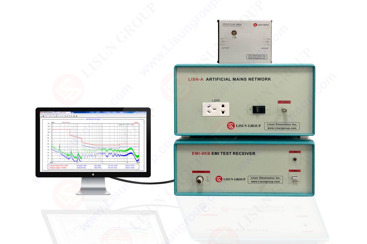
The proper use of EMI receiver in advanced laboratories and compliance facilities is important to obtain accurate electromagnetic measurements. Electronic systems are becoming densely connected, high-speed and compact systems, hence increasing the complexity of the undesirable interference. The EMC testing engineers have to depend on precision devices, uniform procedures, and punitive best practices. False failures, incorrect readings or poor design decisions can all be made even by minor mistakes.
By profession, users realize that there is more than simple switching and scanning with a device when it comes to using an EMI receiver. Preparation, calibration awareness, system validation, environmental control, correct treatment of the probe and correct interpretation of the detector responses are all part of it.
Engineers would want to fully comprehend the inner architecture of an EMI receiver before utilizing it. A front-end RF chain, preselectors, attenuators, IF filters, detectors and digital processing units are available in the receiver. Good knowledge of the impact of each item on the accuracy of the measurement assists the professionals in making improved decisions when setting up.
A preselector, as an example, isolates the recipient of overloading by high-power out-of-band signals. CISPR bandwidths are set by filters. Internal attenuators emphasize the front end and can diminish sensitivity. More advanced receivers such as those produced by LISUN incorporate smart gain control which reduces the possibility of overload and also maintain dynamic range.
An EMI receiver has to be thermalized before it could record the real data. Internal filters, mixers and filters vary in slight changes with shifts in temperature. The frequency accuracy and amplitude measurements can be influenced, providing wrong values; measurement needs to start too late after turning on the unit.
The duration of the warm-up is at least 20-30 minutes which can be permitted by professionals. Depending on the conditions of the environment, high precision EMC facilities may expand this time. Long measurement sessions of several hours are particularly critical and require stabilization because stable baseline performance is important.
The reliability of EMC testing requires a controlled environment. Measurement quality depends on temperature, humidity and electromagnetic noise. The practitioners will get the receiver to a clean electromagnetic area and get him or her out of all those cables, switching adapters or other wireless devices which could cause interference with the results.
During radiated testing, ambient RF within the communication towers or WiFi devices around the Wi-Fi receiver may disrupt the receiver. Spectrum scans before commencing measurements are an experience that is generally done by experienced engineers to ensure that ambient peaks are avoided. Unwanted noise in conducted testing may be caused by ground loop or improper bonding. In cases that assure good grounding and power cleanliness, the receiver should have a higher chance of measuring the actual emissions of the tested device.

Specific detectors including peak, quasi-peak, average, and RMS have to be used in order to test EMC-compliant with CISPR. There are as many detectors as ways of interpreting the signal. A professional should grasp the circumstances and occasions when each detector is necessary.
• Peak detectors estimate peak instantaneous interference, and are used when scanning at a start.
• Quasi-peak detectors use weighting which indicates the disturbance effect on radio receivers.
• Average detectors are used to determine modulated noises with broadband.
• Energy based evaluations are given by RMS detectors.
Overreliance on peak measurements is a common error, which is not supported by the subsequent verification of quasi-peaks. The reason why professionals never make decisions that rely only on peak results is that only in the case when the peak is lower than the limit line by a comfortable margin, such a decision is finalized.
Signal path Signal path Attenuators and preamplifiers manipulate the signal path. When used incorrectly, there will be overloading or loss of sensitivity. In case of overload due to the strong signal coming in, it can give distorted readings or spurious emissions. In case of the weakness of signals, significant emissions might not be detected.
Scans on initial scans are adjusted according to the experienced engineers. In the event of noise floor being too large, introduction of preamplifier can be considered though this has to be permitted by the measurement standard. In the case of conducted EMC testing, the strong signals of switching power supplies or unstable behavior of the DUT should never be overdriven by the EMI receiver.
Validating the entire chain of measurement before the actual product is tested is one of the most significant professional habits. These consist of the verification of the performance of:
• Cables
• LISNs
• Antennas
• Coupling networks
• Near-field probes
• Switch boxes
• Pre-amps
Professionals use known calibration sources to establish that the EMI receiver is responsive before connecting a real DUT. This prevents the frequent error of operational errors with product failures.
Professionals do not make fast or hasty scans. They have systematic scan policies:
• Begin with sweeps in frequency.
• Determining regions of potential peaks.
• Narrow down with smaller span widths.
• Apply CISPR filters
• Detailed insight Switch detectors.
• Take advantage of time-domain scan capabilities
There are also receivers like the EMI models of LISUN which offer mode switching, frequency markers and fast scan algorithms which are useful to quickly isolate problem frequencies without compromising the accuracy of the result.
The distinction between search mode and final measurement mode is also known by the professionals. Peaks are found on the first scans, however, final compliance scans should obey precise rules on detectors and bandwidth.
Poor grounding results in unstable bases and noise pick up. Testing of LISNs must be done very carefully to control grounding, cable routing and placement of power lines. The stable cable positioning, distance, and height of the antenna are required in radiated testing.
Best practices include:
• Storing the cables straight and not coiled up.
• Keeping the cable location between tests constant.
• Bonding equipment to chamber ground plane.
• The unnecessary adapters or splitters should be avoided.
• It involves proper use of ferrites.
New operator training does not involve treating cable routing as an afterthought part of the test set-up but a component of it.
The EMI receiver and several probes are applied in investigation stages. Fields near the circuit are sensed with a near-field probe, whereas radiated flows are sensed with an antenna. Professionals know that near field measurements show root causes, but can not directly compare it to compliance limits.
Near-field probes are used by engineers in the process of troubleshooting and EMI receiver in the formal CISPR-compliant results. Both are wrongly mixed, which results in misunderstanding. Diagnostic and compliance results have their own data logs recorded by professionals.
In order to be accurate it requires calibration. Professional send their EMI receivers to be calibrated periodically as recommended by the manufacturers, usually once every year. Depending on the intensity of usage, the high-accuracy EMC labs can be recalibrated.
Regular service entails:
• Inspection of connector wear.
• Checking cables to determine whether they are damaged.
• Cleaning internal ventilation channels.
• Updating firmware
• Checking front end security
To design a mastery of an EMI receiver, far beyond simple EMC testing takes place. It requires intense technical knowledge, meticulous installation, tight control of the environment, accurate detector operation, accurate test results interpretation, and rigorous test equipment maintenance by professionals. Such best practices guarantee precise, reproducible and reliable results of EMC testing even in complicated electronics. Having a professional receiver, developed procedure, and a friendly manufacturer like LISUN, engineers are able to detect problems of interference and meet international EMC guidelines.
Lisun Instruments Limited was found by LISUN GROUP in 2003. LISUN quality system has been strictly certified by ISO9001:2015. As a CIE Membership, LISUN products are designed based on CIE, IEC and other international or national standards. All products passed CE certificate and authenticated by the third party lab.
Our main products are Goniophotometer, Integrating Sphere, Spectroradiometer, Surge Generator, ESD Simulator Guns, EMI Receiver, EMC Test Equipment, Electrical Safety Tester, Environmental Chamber, Temperature Chamber, Climate Chamber, Thermal Chamber, Salt Spray Test, Dust Test Chamber, Waterproof Test, RoHS Test (EDXRF), Glow Wire Test and Needle Flame Test.
Please feel free to contact us if you need any support.
Tech Dep: Service@Lisungroup.com, Cell/WhatsApp:+8615317907381
Sales Dep: Sales@Lisungroup.com, Cell/WhatsApp:+8618117273997

LISUN’s Motor-Operated Tool | Power Tool Testing solutions strictly comply with a range of core international standards, providing full support for safety and electromagnetic compatibility (EMC)...

LISUN’s transformer test solutions meet IEC 61558-1, IEC 60076-1, IEC 62041 standards. Covering safety, performance, EMC tests, ensuring transformers comply with global requirements.

LISUN’s household and appliance switch testing solutions meet IEC 60669, IEC 61058, IEC 62271 standards. Covering electrical, mechanical & EMC tests for global compliance.

For the CFL design and manufactory, LISUN can supply a full quality control test solution, including photometric, colorimetric, electricity, flicker, IES candela distribution, surge test, electrical...

 中文简体
中文简体
