
LM-79 Moving Detector Goniophotometer (Mirror Type C)
LSG-6000

High Precision Rotation Luminaire Goniophotometer
LSG-1890B

High Precision Rotation Luminaire Goniospectroradiometer
LSG-1890BCCD

Goniophotometer for Automotive and Signal Lamps
LSG-1950

Goniophotometer for Traffic Signal Lamps
LSG-1950S

Compact Goniophotometer
LSG-1200A

Near Field Moving Detector Goniophotometer
LSG-1900B
Select an organization
to browse standards
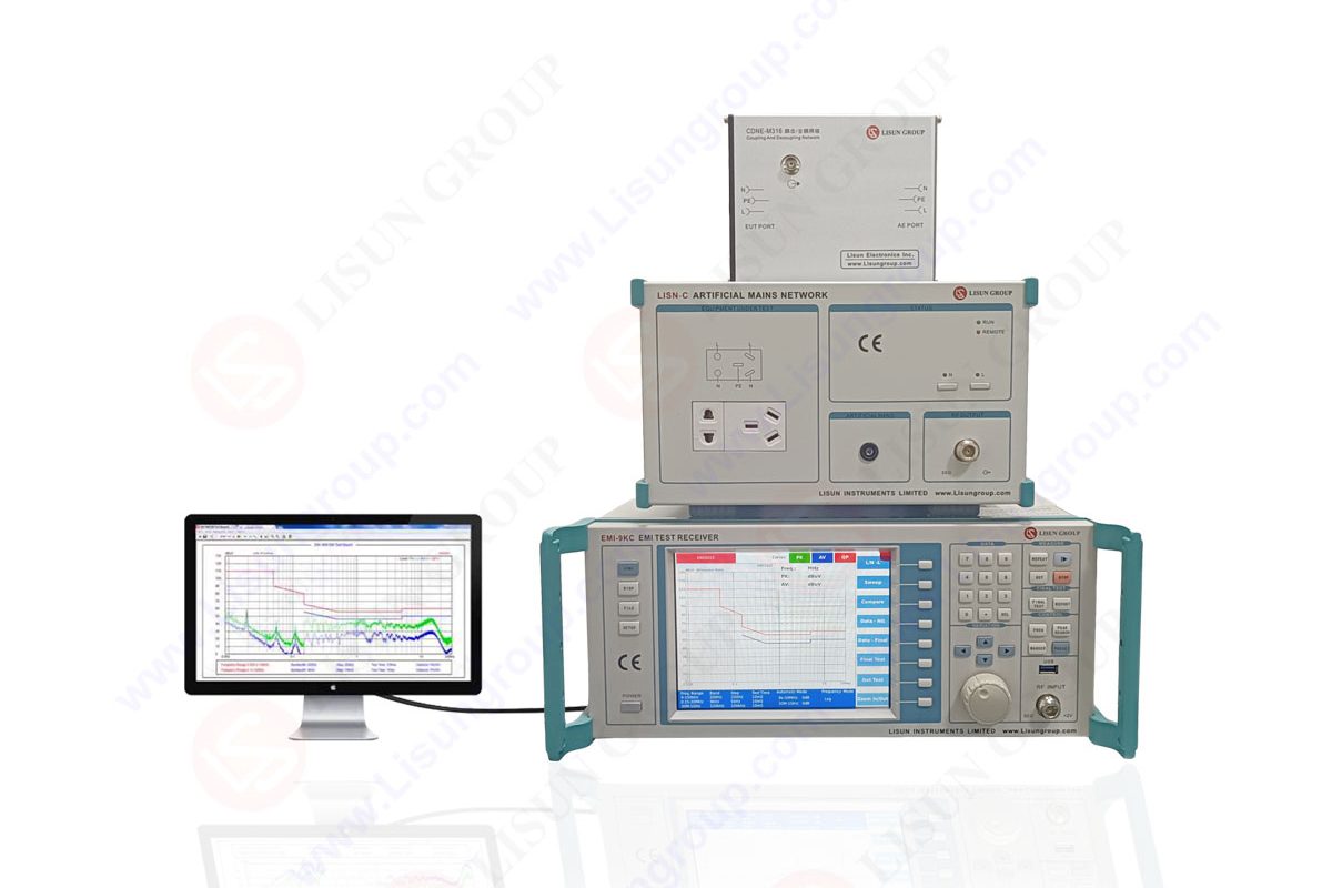
In case a product fails the EMC tests, the engineers are not only faced with a problem of identifying the failure, but also finding answers to the question of why the failure has occurred and how to correct the failure and ensure that it minimally fails. Electronic networks in the modern world have switching converters, oscillators, microcontrollers, wireless modules, and cables that create complex patterns of interference. Together with an appropriately designed line impedance stabilization network, the instrument offers an in-depth view, allowing to identify problem frequencies, emission origins, and confirm a fix to be correct. Strict compliance with performance and reliability requirements where it is mandatory to minimize redesign time and certification is needed in high compliance environments, which require effective troubleshooting.
The reason why the EMI-9KB is popular in world laboratories, even those which operate the LISUN equipment is due to its wide features on diagnostic. These capabilities are particularly useful when the products fail at radiated or conducted emission limits and need more intricate investigation. This paper details why engineers can use the spectrum analysis features of the EMI-9KB to do highly advanced troubleshooting without having to repeat fundamental EMC theory or overall compliance requirements.

Failed EMC tests can hardly be associated with one apparent cause. Switching power supplies, clock generators, PCB trace resonance, inadequate grounding, cable radiation or insufficient filtering can be the sources of emissions. A failure can be represented by high peak at a single frequency, yet the underlying cause can have a combination of several interacting items..
Simple measurement devices merely indicate that a device is functioning or not. Effective troubleshooting however requires more analysis such as:
• Locating sources of precise emissions.
• Harmonics and subharmonics that were observed.
• The modulation effects can be measured.
• Knowing the effects of cables and enclosures structures.
• Assessing component level behavior.
The EMI-9KB offers the answer of resolution, detector precision and diagnostic flexibility that colors in these latent problems and caters engineers on the appropriate corrective measures.
Test bench needs to be set up before subjecting the EMI-9KB to a detailed analysis. Proposed conducted emissions demand a line impedance stabilization network which has been properly calibrated. The use of radiated emissions demands suitable antennas, turntables and absorption lined conditions.
Grounding, location of probes and routing of cables should also be considered by the engineers. Undesirable bench arrangement may add errors to the troubleshooting process. This means that prior to the investigating the failure, baseline measurements must be conducted in order to test the measurement chain.
Detailed frequency signatures by themselves are one of the best features of EMI-9KB. In case a device does not pass EMC tests, the first thing is to determine significant peaks in the spectrum.
• Clock harmonics
• The switching converter frequency
• Digital bus transitions
• Resonance from PCB traces
After knowing the points of the emission, it is possible to identify the corresponding circuit sections and match them with the points of the emission. All this is based on this correlation as the cornerstone of troubleshooting.
Table: Typical EMC Failure Patterns and Likely Causes
| Spectrum Pattern | Likely Cause | Notes |
| Strong narrow peaks at fixed intervals | System clock harmonics | Often visible at multiples of CPU or oscillator frequency |
| Broadband noise rising at high frequencies | Switching power supply | Caused by MOSFET transitions and diode recovery |
| Peaks modulating with load changes | DC converter instability | Indicates loop compensation issues |
| Emissions strong only on cables | Common mode currents | Often due to poor grounding or cable shielding |
| Peaks shifting when enclosure is touched | Enclosure resonance | Caused by floating grounds or poor bonding |
This table will be used with the EMI-9KB in order to do advanced troubleshooting in case of failure during EMC tests.
The EMI 9KB has peak, quasi peak, average and RMS detectors. Both the detectors distinguish various features of the interference. In the analysis of the failure points:
• Peak detector-determines maximal instantaneous emissions.
• Quasi peak detector indicates the degree of upset of communication equipment.
• Mean detector is used to determine broadband noise.
• Non-peaking permits constant power of a detector
By switching these detectors, engineers can get to know whether a peak is actually problematic, or it is just a one-time spike.
For example, a peak that only fails on peak detection but passes quasi peak cannot be a functional fault, but a transient. Conversely, uninterrupted quasi peak failure is a cause of a serious source of emissions that need to be tackled.
The engineers can determine the conducted noise in AC mains or DC supply by using the EMI 9KB with a line impedance stabilization network. Troubleshooting focuses on:
• Input filter performance
• Differential mode harmonics
• Common mode interference
• Ground reference distribution
Using near field probes, engineers are able to monitor noise movement originating at components to cable.
In case the noise is caused by MOSFET switching, snubber circuits or damping resistors can be required. Ferrite beads and common mode chokes can be used in case the common mode noise is predominant. EMI-9KB spectrum allows ensuring that every remedial action lowers certain emission peaks.
Engineers need to investigate:
• Enclosure openings
• Cable orientation
• PCB trace resonance
• Antenna-like structures are wires.
• Ineffective shielding of switching sections.
The radiated emissions can be in the form of stiff peaks around clock harmonics or switching frequencies. The EMI 9KB enables the engineer to record near field patterns and infers the variations in emissions under the following conditions:
• Touching the enclosure
• Moving cables
• Adding shielding tape
• Adjusting PCB grounding
• Restructuring internal elements.
Spectrum variations indicate directly, which components of the device are inducing the radiated failure.
Troubleshooting is an advanced process that involves frequency domain analysis as well as time domain observation. Time domain tools are useful in isolating intermittent emissions which are generally not easily detected through the conventional sweep analyzers. Minor design decisions of small layout designs, including trace length, ground stitching, or cable routing, can cause a great amount of difference between emission behavior. These insidious sources are detected by time synchronous measurements.
One of the frequent reasons of unsuccessful EMC test results is poor grounding. Floating ground reference points, ground loops, and discontinuous shielding may provide undesirable return interference paths.
With near field probes and the EMI-9KB, engineers are able to test:
• Shield continuity
• Ground bond strength
• Path of return currents
• Hotspots in the area of switching components
When engineers alter a design in a failure related to EMC, the EMI-9KB will verify that the corrective action was successful. The waveforms can be compared and contrasted at high resolutions and this allows the engineers to analyze:
• Cutting down the harmonic levels
• Lower common mode current
• Improved cable radiation
• Stable filter response
• Smoother switching
A line impedance stabilization network is useful in ensuring that measurement consistency is embarked in validating input filter improvements or power supply redesigns.
The failed EMC tests cannot be troubleshooted without more than elementary measurement. Engineers should also find exact sources of emissions, signal behavior, filtering performance and grounding and shielding validation. Spectrum analysis instruments like EMI 9KB have the depth and precision needed to make diagnosis of complex failures. The analyzer is a potent tool that corrects emission issues and makes them comply, when used with a well-designed line impedance stabilization network. The highly-developed tools and comprehensive set up besides systematic analysis with professional equipment like LISUN offers, can guide one through the most difficult EMC failures and will provide perfect product functionality.
Lisun Instruments Limited was found by LISUN GROUP in 2003. LISUN quality system has been strictly certified by ISO9001:2015. As a CIE Membership, LISUN products are designed based on CIE, IEC and other international or national standards. All products passed CE certificate and authenticated by the third party lab.
Our main products are Goniophotometer, Integrating Sphere, Spectroradiometer, Surge Generator, ESD Simulator Guns, EMI Receiver, EMC Test Equipment, Electrical Safety Tester, Environmental Chamber, Temperature Chamber, Climate Chamber, Thermal Chamber, Salt Spray Test, Dust Test Chamber, Waterproof Test, RoHS Test (EDXRF), Glow Wire Test and Needle Flame Test.
Please feel free to contact us if you need any support.
Tech Dep: Service@Lisungroup.com, Cell/WhatsApp:+8615317907381
Sales Dep: Sales@Lisungroup.com, Cell/WhatsApp:+8618117273997

LISUN’s Motor-Operated Tool | Power Tool Testing solutions strictly comply with a range of core international standards, providing full support for safety and electromagnetic compatibility (EMC)...

LISUN’s transformer test solutions meet IEC 61558-1, IEC 60076-1, IEC 62041 standards. Covering safety, performance, EMC tests, ensuring transformers comply with global requirements.

LISUN’s household and appliance switch testing solutions meet IEC 60669, IEC 61058, IEC 62271 standards. Covering electrical, mechanical & EMC tests for global compliance.

For the CFL design and manufactory, LISUN can supply a full quality control test solution, including photometric, colorimetric, electricity, flicker, IES candela distribution, surge test, electrical...

 中文简体
中文简体