
LM-79 Moving Detector Goniophotometer (Mirror Type C)
LSG-6000

High Precision Rotation Luminaire Goniophotometer
LSG-1890B

High Precision Rotation Luminaire Goniospectroradiometer
LSG-1890BCCD

Goniophotometer for Automotive and Signal Lamps
LSG-1950

Goniophotometer for Traffic Signal Lamps
LSG-1950S

Compact Goniophotometer
LSG-1200A

Near Field Moving Detector Goniophotometer
LSG-1900B
Select an organization
to browse standards
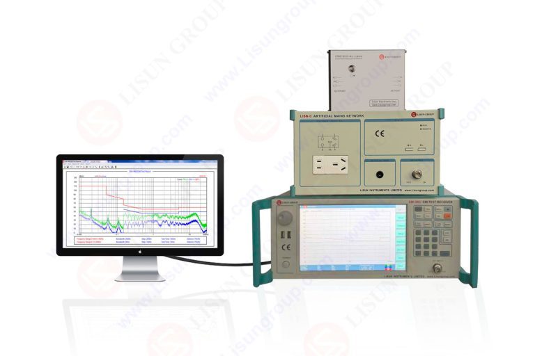
The main measurement device in conducted and radiated emission tests is an EMI test receiver. Antennas LISNs and test sites get significant coverage but the receiver arrangement ultimately defines the distinction between measured values of true emissions or artifacts of set-up and signal processing. In pure EMC testing facilities there is a tendency to separate limits by a few decibels. Virtually, small flaws in configuration of bandwidth detector timing or reference level choice can transform a pass to a failure. Further methods of configuration work on the removal of the appropriate signal under specific criteria and repeatability across the laboratories and test campaign.
Receiver configuration is not a single time event. It should also be scaled to the range of emission type frequencies and product response and still conform to the standard. Knowledge of the effects of the individual parameters of the receiver on the measurement result is critical in certification because engineers must provide defensible results.
Precisely matching the selection of the frequency range resolution bandwidth against selection of the detector is the basis of proper EMI measurement. There are standards defining bands of measurement of the effect of radio services amid interference. The receiver should be programmed to do scanning in the right start and stop frequencies without gaps or overlaps that can bias findings.
The sensitivity and noise discrimination depend on the resolution bandwidth that is selected. A more limited bandwidth enhances noise floor, but may oversize broadband emissions. A broader bandwidth is more efficient in capturing energy but it adds more noise. Standards specify bandwidths of discrete frequency ranges and advanced configuration provides the seamless way of the receiver between bandwidths change when the scan is performed automatically.
Selection of detector is also very vital. Peak detection determines the worst emissions but forms an overstatement of interference effects. Quasi peak and average detectors weight by repetition rate/duty cycle. Strict compliance expects that time and charge discharge constants of the receiver match with the behavior of detectors detailed under the standard. Advanced users also set dwell timing depending on signal behavior to ensure that detectors have settled to the extent that they capture values. Any failure to do that will lead to inconsistent readings which are different in scans.

Dynamic range control is used to make sure that the EMI test receiver is working within its linear range of measurements. Excessively high setting of the reference level will cause an increase in sensitivity and conceal marginal emissions. Setting it too lower can cause overloading and intermodulation which cause false peaks. Advanced configurative entails iteration of reference level from preliminary scans and anticipated emission profiles.
Preselection filters are important in guarding the receiver front end as well as enhancing selectivity. Out of band signals desensitizing the receiver are attenuated by proper preselector configuration. To achieve the wideband scans automated preselector tracking applies ideal filtering at frequencies. The hard cases which may require manual override include strong broadcast signals which may overpower some of the bands.
This balance includes attenuation setting. Internal attenuation shields the receiver whilst making the measurement less sensitive with high levels. Correction factors should be taken into consideration with respect to external attenuation. Further users report attenuation states so that they are traceable and the reported values are true field strength or the conducted voltage.
A lot of modern devices produce emissions, whose variations change over time owing to power management states knowledge bursts or counter measures. These behaviors can be missed in the scans made at static frequency domain. Time domain awareness has also been introduced into advanced receiver configuration to obtain intermittent emissions.
Triggered measurements enable the receiver to give attention to activity periods. Isolating the emission events in device operation or blocking by time gated analysis, engineers identify the important emission events. This will result in better repeatability and minimize the background noise which may be irrelevant.
Accuracy is also dependent on the sweep speed. Fast sweeps save test time, but are not considered able to stabilize detectors on fast-changing signals. Reduced speed e.g. slower sweeps enhance accuracy, but expose to drift and environmental noise. Complex control balances the three aspects of the detector requirements, stabilization of signal and speed of the side-by-side sweeping of the detector. Strict compliance testing conservative sweep settings are usually warranted in order to provide defensible results.
The receiver setup has to include correction of antennas cables LISNs and preamplifiers. These factors depend on frequency and directly impact on those values reported. Advanced users will handle correcting table cautiously in ensuring it matches to the specific hardware being used and that it is updated with the calibration records.
Accuracy is based on MTM of the EMI test receiver. Periodically, frequency accuracy amplitude linearity and detector response have to be confirmed. Configuration involves the selection of appropriate calibration profile and any offsets are made. At the regions of measurement that are near some level of uncertainty is critical. Knowledge of receiver contribution to total uncertainty (margin and risk) assists the engineers to judge.
There is also the influence of environmental stability on uncertainty. Reference oscillators and receiver gain can change due to changes in temperature. Verification of baseline noise and providing warm up Time is a viable configuration method that favours even results.
Nowadays EMC laboratories are the places where complexity is handled by automation. Complex configuration involves use of some profile which is preset and adjusted to certain standards. These profiles secure key parameters like type of bandwidth detector and dwell time but they leave flexible parameters that are allowed. This discourages variability in operators and enhances consistency between tests.
Another technique is automated rescans. Once an initial peak scan has been performed the receiver is set to remeasure suspect frequencies with either quasi peak or average detectors with longer dwell times. This focused solution enhances precision without subjecting the test too much time.
Tracing is improved with data logging and reporting systems. Audits and reanalysis would be enabled by recording raw receiver settings and results, in case the standards change. The integration is simplified by equipment ecosystems used to test EMC. EMI receivers and software that are offered by suppliers like LISUN make it easy to achieve standardized configuration workflow and automatic generation of compliance reports.
The environment of receiver can not be separated with the test environment. Routing of grounding cable and retribution behavior of accessory has an impact on the appearance of the receiver. Advanced setup also involves checking the level of background noises and varying the receiver sensitivity based on the result. When ambient signals reach limit levels only the configuration changes can not compensate and mitigation to the environment is necessary. More sophisticated users hold configuration checklists that ensure that receiver settings align with physical setup correct positioning before serious measurements work is underway.
Highly sophisticated settings of the EMI test receiver are prerequisites to high compliance in EMC testing. Measurement validity is achieved by proper alignment of frequency range bandwidth and detector behavior. Time domain awareness and uncertainty control in dynamic range management make the accuracy further more refined. Put together with automation profiles, controlled calibration and careful interweaving with the environment receiver configuration of the test environment is an impressive weapon, rather than a competitor. The results obtained by the application of these techniques are repeatable defensible and acceptable across regulatory regimes.
Tags:EMI-9KB
LISUN’s Motor-Operated Tool | Power Tool Testing solutions strictly comply with a range of core international standards, providing full support for safety and electromagnetic compatibility (EMC)...

LISUN’s transformer test solutions meet IEC 61558-1, IEC 60076-1, IEC 62041 standards. Covering safety, performance, EMC tests, ensuring transformers comply with global requirements.

LISUN’s household and appliance switch testing solutions meet IEC 60669, IEC 61058, IEC 62271 standards. Covering electrical, mechanical & EMC tests for global compliance.

For the CFL design and manufactory, LISUN can supply a full quality control test solution, including photometric, colorimetric, electricity, flicker, IES candela distribution, surge test, electrical...

 中文简体
中文简体
